TL;DR
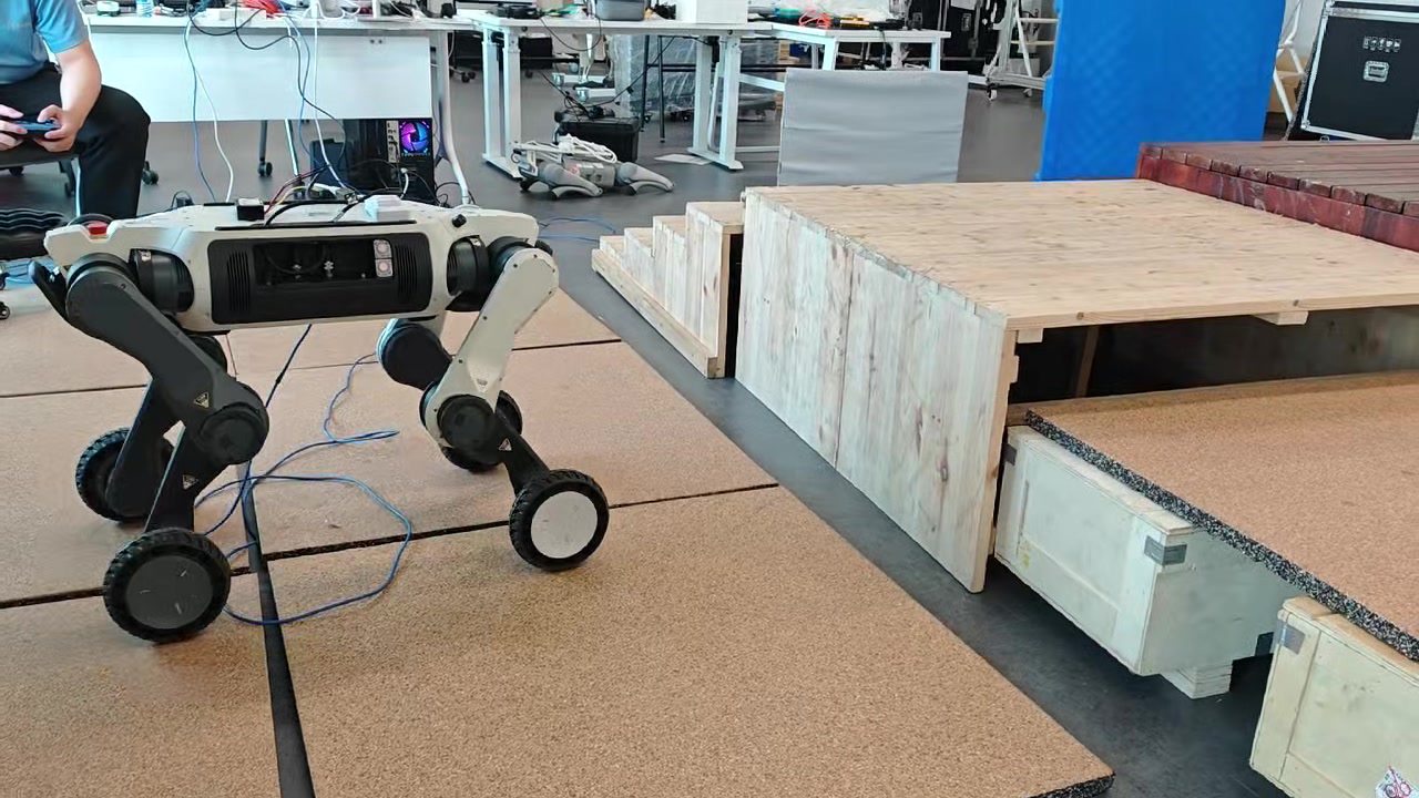
To give ArcDog (and a future humanoid) drivers with full control over the low-level motor algorithm, we built the stack ourselves rather than gluing off-the-shelf parts: three driver revisions (V1 stacked → V2 with through-hole → V3 single-board, 72 mm), firmware designed as a “communication bridge + FreeRTOS app + high-rate FOC” architecture running an 80 kHz FOC loop with current sampling latched 67 ns from PWM center, EtherCAT / CAN-FD daisy-chained across many motors plus a CAN2USB adapter that exposes MIT / LK / DJI motors under one MIT-style API, an in-house-designed 48 V / 8.2 Ah / 100 A soft-pack battery, and a 0–200 Nm bench-built dynamometer.
1. Why build it ourselves
Off-the-shelf drivers (Damiao, Haitai, etc.) work, but as a research platform we need:
- Mechatronic dimensional freedom — joint diameter, through-hole routing, and connector orientation are hard mechanical constraints; commercial drivers are sized for specific motors;
- Open algorithmic depth — we want DTC and SPTFC (single-period torque-forecast control) on top of FOC, which closed firmware cannot host;
- Supply chain control — TI parts faced +125% tariffs at one point, so we need a fast fallback to Microchip silicon.
Same logic on the battery: the voltage / current / form factor we need is not on the LiPo shelf.
2. Driver Hardware: V1 → V2 → V3
V1: stacked, B2B-interconnected
V1 split power stage / logic stage / inductive position sensor into three 70 mm round PCBs, mated through B2B connectors with washers and air gaps for thermal isolation (Fig. 1).

Fig. 1 — Stacked architecture: power, logic and position-sense on separate boards.
V2: keep a 15 mm through-hole
V2 carved a 15 mm hole through the center so the joint power cable can pass through the driver. With 1.6 mm boards, the mechanical thickness is 9.8 mm at the boards and 15 mm at the tallest component. This is what made it actually fit inside a hip joint.
V3: single-board, commercial-grade footprint
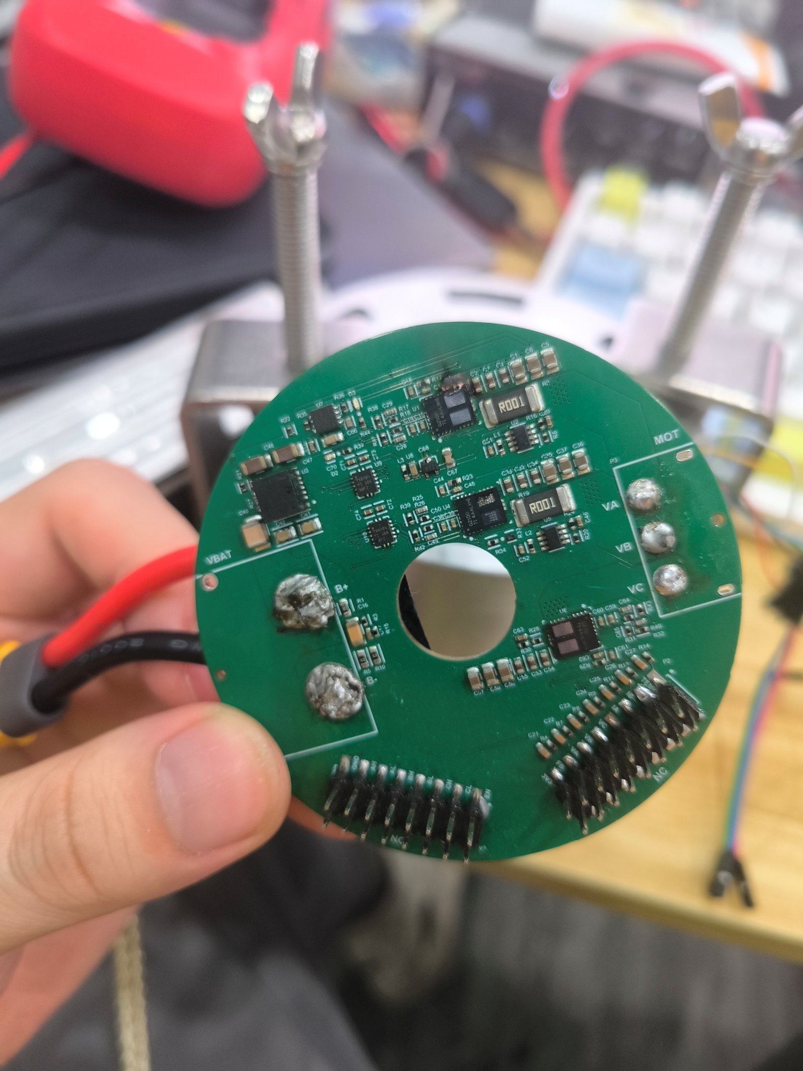
Fig. 2 — V3 driver: power + logic + position-sense on a single 72 mm board with a center hole, dimensionally on par with the Damiao reference.
V3 collapses power and logic onto one board and shrinks the diameter to 72 mm while keeping the through-hole. Re-laid out with Wenhao; under tariff pressure we replaced part of the bill of materials with Microchip silicon (we already had a USB2CAN reference using that family). Boards have come back from JLC and SMT is in progress.
3. Firmware: FreeRTOS + 80 kHz FOC
3.1 First refactor: communication-bridge decoupling
I split the code into two processes:
- Communication bridge — long-running, owns EtherCAT/CAN parsing, the DS402 state machine, and object-dictionary ↔ physical-unit conversion;
- User process — independent, talks to the bridge over a message queue with a {mode, torque, position, velocity} tuple. The interface is intentionally MIT-style so it’s obvious to read.
Net effect: protocol changes / new modes / new error-recovery logic don’t touch user code; killing the user process doesn’t kill the bridge; switching UI frameworks no longer requires rewriting the controller (the QMake lock-in goes away too).
3.2 Second refactor: move onto FreeRTOS
For V3 the algorithm runs on the chip (Microchip). FreeRTOS lets us split:
- High-rate task (80 kHz): FOC loop + current overcurrent protection
- Low-rate task (1 kHz): USB / CAN, slow peripherals
Hot path optimizations:
- Selected float ops → fixed-point;
- Trig functions → lookup table;
- Branches → ternary expressions to dodge mispredict penalties;
- MCPWM center-triggered ADC sampling with double-buffered DMA, decoupling ADC from algorithm.
Result: algorithm steady at 80 kHz synchronized to PWM (raw ceiling ~120 kHz). ADC-to-PWM-center latency is 67 ns — Fig. 3 shows the SysConfig: 12-bit, ADCDIV=1, SAMC=1, TAD=66.667 ns.
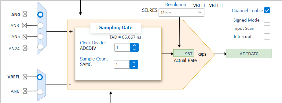
Fig. 3 — ADC channel + sample rate in SysConfig: 937 ksps single channel, TAD 66.667 ns.
3.3 An expensive lesson
In the name of “clean threads” I once put overcurrent protection in the 1 kHz low-rate task. During a high-torque test the protection couldn’t trip in time and the A-phase upper bridge on one board burned out. Lesson: protection lives in the same 80 kHz loop as the FOC — never trade real-time guarantees for code prettiness.
3.4 The FOC algorithm
Standard PMSM FOC (Park / Clarke / SVPWM / current PI). Until our in-house position sensor is ready we estimate the rotor angle using a Hall + observer combination. Yigang Lin owns the algorithm — Simulink → TI/Microchip auto-codegen → our FreeRTOS framework. Next steps push DTC plus torque prediction into a unified single-period torque-forecast control (SPTFC) to shorten command-to-actual-torque latency.
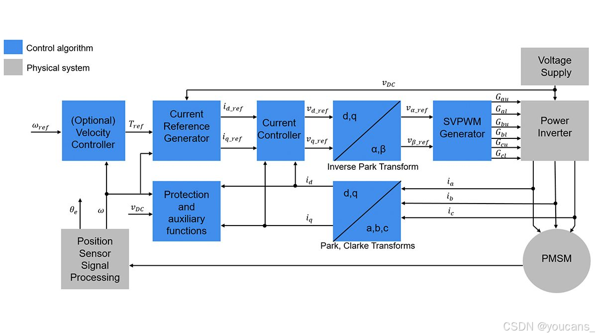
Fig. 4 — PMSM FOC block diagram (reference, for orientation).
4. Communication: EtherCAT + Multi-Protocol Adapter
4.1 EtherCAT bus + a PDO-mapping trick
Quadrupeds and humanoids run a dozen-plus joint motors on one bus, so we use EtherCAT (PHY 100 M, CAN 1 Mb/s per CAN segment) on top of an open-source reference. One EtherCAT line carries up to 128 slaves in our current build.
Switching motor mode (position / velocity / torque / custom) typically takes 6 + 2N SDO transfers with OP↔SAFE-OP transitions, which doesn’t fit a 100 Hz loop. Our trick:
At init time, build a PDO mapping whose IO-MAP size is the max across all modes. Mode switches then need only one SDO + one PDO write, no IO-MAP renegotiation, with a final PDO write to clear errors.
Switch latency drops from milliseconds to sub-millisecond — well within budget.
4.2 CAN2USB multi-protocol adapter
For bench tests and small projects we built a CAN2USB adapter whose firmware speaks MIT / LK / DJI / Lingkong at the lower edge but exposes a single MIT-style API at the upper edge (enable / disable / motion).
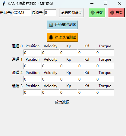
Fig. 5 — Host-side controller (MIT layer over four CAN channels).
A small gotcha: MIT replies with full state on every command; LK replies only an ACK on enable/disable. We patched the firmware to issue a status query immediately after enable/disable so the upper layer sees a consistent view across vendors.
5. Battery PACK: co-developed with the cell maker
What the robot needs isn’t a stock 6S/12S LiPo, it’s a 48 V / 8.2 Ah nominal / 100 A continuous / 150 A peak soft-pack with a custom envelope to fit the chassis. Our split:
- We design the busbar plate, BMS and enclosure;
- The cell company matches and ships cells to the assembly factory;
- The assembly factory builds the PACK with our busbar / BMS plan, tests it, and ships it back; we drop it into the enclosure.
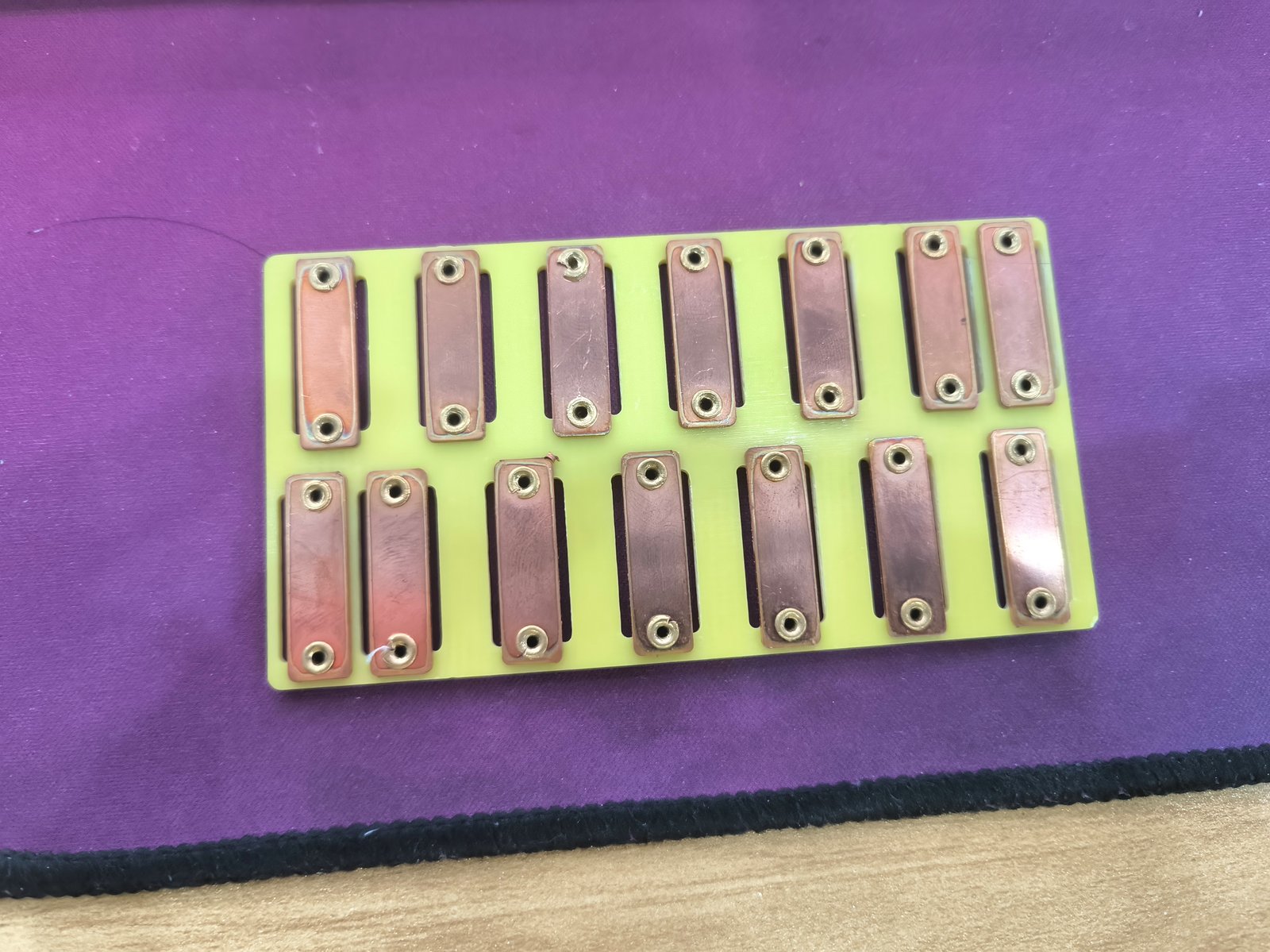
Fig. 6 — Custom busbar plate (copper strips, dual-layer layout).
Around the pack, the power system exposes multiple rails: 48 V heavy-load (HMK connectors, 100 A nominal / 150 A peak per channel with per-channel fuse) for the limb motors; 19 V isolated 200 W for the logic stage; 5 V isolated 40 W for sensors; a 500 W “Mickey Mouse” inlet for charging.
6. The In-house Dynamometer
6.1 Hardware
We bought a DYN-200 dynamic torque sensor (0–200 Nm) and built a fixture around it: tested motor on one side, load motor on the other, joined by interchangeable flange adapters — hard aluminum (≤ 40 Nm) or carbon-steel for higher torque. Swapping motors only requires swapping the flange and clamps; no main-body teardown.
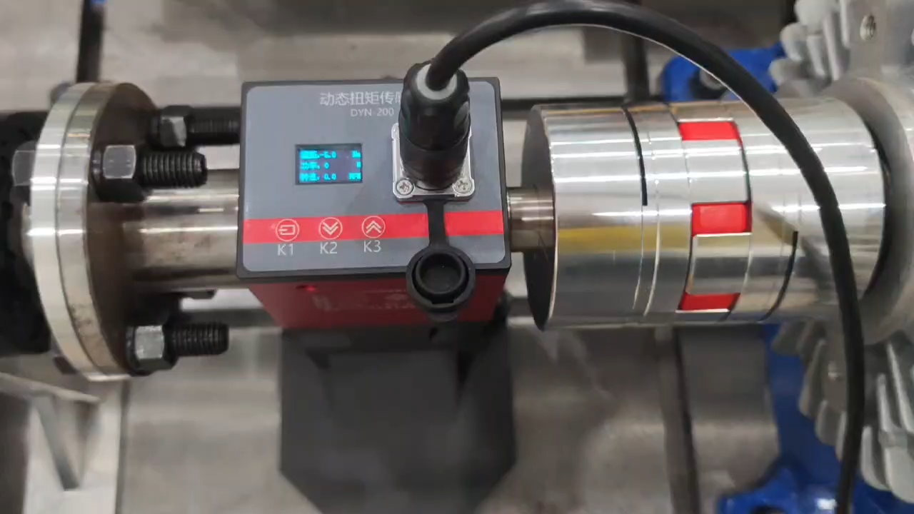
Fig. 7 — The bench: torque sensor (red) between coupling and motor.
A single external converter drives the load motor, replacing the bulky variable supply we used early on.
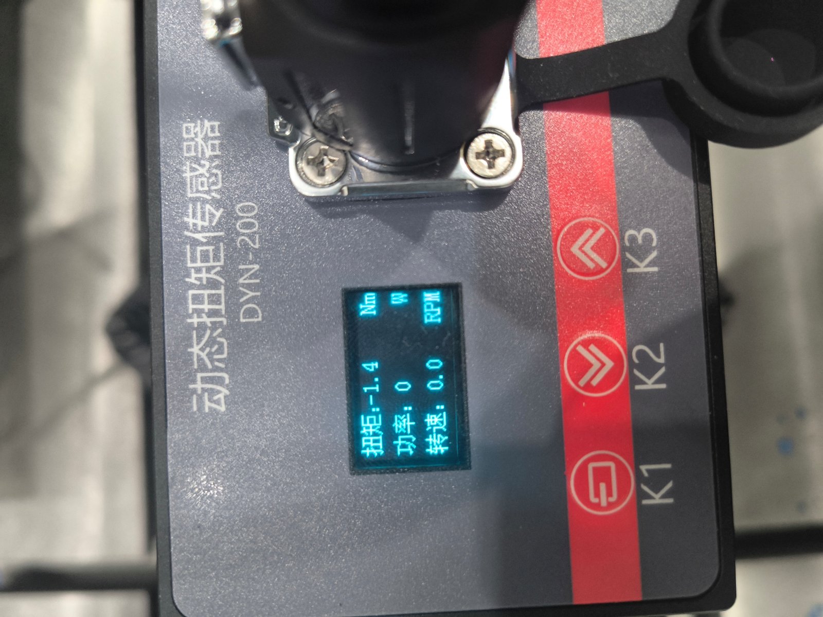
Fig. 8 — DYN-200 readout: torque / power / RPM.
6.2 Software + calibration
A simple cross-platform UI sits on top of the CAN2USB multi-protocol layer from §4.2 — the same benchmark script runs against motors using different vendor protocols and produces directly comparable data:
[Benchmark] Applied torque = 1 Nm
[Benchmark] Applied torque = 5 Nm
[Benchmark] Applied torque = 10 Nm
...
[Benchmark] Applied torque = 18 Nm
We benchmarked an LK motor (vendor didn’t ship a current-to-torque table at first; they sent one later). We ran our own sweep → calibration → re-test loop and reached:
< 0.1 Nm error after calibration, in our test conditions.
The 200 Nm range is plenty for small/medium motors; bigger humanoid motors will need extra safety design.
7. Status & Next
| Item | Status |
|---|---|
| EtherCAT master/slave sync, custom mode, auto error recovery | ✅ |
| Up-to-128-slave parallel control framework | ✅ |
| Firmware refactor (comm bridge + FreeRTOS) | ✅ |
| 80 kHz FOC + 67 ns ADC-to-PWM latency | ✅ |
| V3 driver (72 mm single-board) | Boards back, SMT in progress |
| High-power version (humanoid, 16–81 V / 53 A phase) | BoM locked, kicks off once V3 validates |
| In-house inductive position sensor | In progress (Zhenxiao) |
| Dynamometer + cross-platform UI + LK calibration | ✅ (< 0.1 Nm error) |
| 48 V soft-pack battery co-development | Spec frozen, in production |
| SPTFC (single-period torque forecast) | Exploration on Microchip silicon |
Next milestones: finish the in-house position sensor so FOC stops depending on third-party encoders, then tape out the high-power board for the humanoid joint motors.