Model Preview
This model has a total size of 11.7 MB, and it may take some time to load. Please be patient.
Abstract
The bio-inspired fin-propelled underwater robot with complex propulsion systems is a novel robotic system concept, which holds promising applications in military detection and civilian photography fields. In this paper, we take the “Rain Feather Electric Eel” as our biomimetic model. Based on the wave-based propulsion mathematical models established by predecessors both domestically and internationally, we designed and constructed an underwater biomimetic robot with flexible maneuverability. An innovative aspect of this design is the use of an odd number of fins to construct the robot model.
The main work and research achievements of the paper include:
-
Morphological and kinematic modeling of the robot based on the kinematic database of fish-like flexible long-fin wave propulsion established by the National University of Defense Technology. Finite element analysis methods were used to calculate the robot’s motion description.
-
Optimization of the dynamic balance equation for “rigid fin swing + flexible fin material deformation.” The study examined the impact of different parameters on the propulsion capability when the fin is subjected to simple harmonic swinging and complex swinging.
-
Design and construction of a three-wave wave propulsion underwater robot model. An orthogonal experimental design method was used to optimize the experimental scheme. From an experimental perspective, the paper investigated the influence of different biomimetic wave fin structural parameters and motion parameters on the robot’s motion performance.
The experimental research demonstrates:
-
The main factors influencing the overall propulsion of the wave-like fins include fin swing frequency, wave number, and the material hardness of the fin surface.
-
The simplest and most effective way to enhance the robot’s motion performance is to increase the frequency of fin swinging.
-
Under the same structural and motion parameters, the propulsion efficiency of soft fin surfaces is significantly higher than that of hard fin surfaces.
The aforementioned research and achieved results provide theoretical and experimental data for the future application of wave-based propulsion in underwater biomimetic robots. This research holds significant theoretical importance for the development of novel underwater biomimetic long-fin wave propulsion vehicles.
Keywords: “Rain Feather Electric Eel,” “Wave Propulsion,” “Three-Wave Fins,” “Biomimetics,” “Biomimetic Fins,” “Orthogonal Experimental Design.”
Abbreviation Explanation
| Abbreviation | meaning |
|---|---|
| BCF | Body and/or Caudal fin |
| CFD | Computational Fluid Dynamics |
| MPF | Media and/or绪论 Paired Fin |
Chapter 1: Introduction
1.1 Research Background and Significance
As is well known, the continuous development of military and maritime strategies in various countries aims to secure technological and military advantages in maritime and coastal regions. China, with its vast maritime geographic environment, places significant importance on the development of maritime strategy. Serving as platforms for marine exploration and carriers for modern underwater weaponry, research into underwater robots is of paramount importance. Due to the complexity of underwater environments, which affects the adaptability and compatibility of robot systems with their surroundings, the highly efficient and adaptative swimming abilities of fish, honed over millions of years of evolution, have become a source of inspiration. Consequently, research based on the principles of biomimetics, focused on propulsion principles, control algorithms, and operational strategies for underwater robots in response to specific environmental cues, has emerged as a primary goal in the international advancement of underwater robot technology.
The excellent swimming techniques of fish have inspired advancements in propulsion systems and the adaptability and interaction capabilities of underwater robots. Fish swimming propulsion patterns and biomimetic propulsion technologies are increasingly becoming hot topics in the field of underwater propulsion. The development of biomimetic technology, computer technology, control technology, and material technology has provided strong support for the research on the theory and methods of controlling biomimetic underwater robots, motion principles, system composition and implementation, control algorithms, and more. Research on novel biomimetic underwater propulsion systems has become a focal point in the current field of underwater robotics research and has yielded a series of achievements.
According to previous literature, the BCF (Body and Caudal Fin) propulsion mode is optimal for high-speed swimming in calm and open waters. However, it is particularly inefficient for scenarios such as slow swimming, maneuvering, rapid acceleration, and turbulent environments. On the other hand, the MPF (Median/Paired Fin) propulsion mode, as utilized by fish like knife fish and butterfly fish with flexible long fins, combines high propulsion efficiency, excellent maneuverability, and stability. It excels in low-speed, agile maneuvering and possesses strong disturbance resistance. Therefore, in terms of developing autonomous underwater vehicles, the biomimetic long-fin wave propulsion mode inspired by fish is of significant reference value.
In the MPF (Median/Paired Fin) propulsion mode, research has been conducted on both dual-fin and quadruple-fin propulsion, but there has been no research on the feasibility of the three-fin propulsion. Therefore, it is crucial to investigate whether the three-fin propulsion mode offers higher propulsion efficiency and advantages such as stability and balance that are not present in dual-fin or quadruple-fin propulsion modes. Autonomous Underwater Vehicles (AUVs) have extensive application prospects and potential value. Many researchers are dedicated to the development of AUVs, and with the deepening of research into biomimetic principles and biomimetic design, biomimetic underwater robots have become a research hotspot in recent years.
This paper primarily focuses on exploratory work in the field of biomimetics related to the three-wave propulsion mode of fish swimming. It encompasses theoretical and experimental research in areas such as biomimetic wave-like fin propulsion mechanisms, the impact of biomimetic wave fin structural parameters and motion parameters on propulsion performance.
1.2 The Current State of Domestic and International Research
With the rapid development of Computational Fluid Dynamics (CFD) technology and bio-inspired imaging techniques in the 1990s, significant progress has been made in the study of the mechanism and principles of the MPF (Median/Paired Fin) propulsion mode. Although the mechanism of MPF propulsion swimming is not yet fully understood, numerous achievements have been made. Table 1-1 provides an overview of some typical international research projects and recent achievements in biomimetic long-fin wave propulsion systems.
| Research Institution (Year) | Biomimetic Object (Propulsion Mode) | Propulsion Mechanism | Adjustable Parameters | Performance |
|---|---|---|---|---|
| University of Hertfordshire, UK (2001) | MPF Wave Propulsion Mode | PBAs (Membrane Actuators) | Wave Frequency, Wave Amplitude | Achieves three-dimensional movement |
| Northwestern University, USA (2003) | “Black Ghost” Fish (Gymnotiform) | Servo Motors | Wave Frequency | Achieves three-dimensional movement and braking |
| Osaka University, Japan (2005) | Skate (Rajiform) | Servo Motors | Wave Frequency, Wave Length | Six degrees of freedom movement, speeds up to 0.4 m/s |
| Nanyang Technological University, Singapore (2005) | Cuttlefish (Amiiform) | Servo Motors | Wave Frequency, Wave Amplitude, Wave Length | Forward and reverse propulsion |
| National University of Defense Technology, China (2004) | Nile Perch (Amiiform) | Classified | Wave Frequency, Wave Length | Forward and reverse propulsion, speeds up to 0.9 m/s |
| Tallinn University of Technology, Estonia (2004) | Skate (Rajiform) | EPA (Artificial Muscles) | Wave Frequency, Wave Amplitude, Wave Length | Propulsion speed of 0.005 m/s, wave amplitude up to 15 mm |
Table 1: Some Typical International Research Projects and Achievements in Biomimetic Long-Fin Wave Propulsion Systems
Tab.1 Some typical international projects and productions on bio-propoulsirs by undulatory fin.
Chapter 2: Overall Design of the Robot System
2.1 Implementation Process of the Underwater Robot
Based on the background research of the project, our project team intends to use algorithms to perform kinematic forward solutions and analysis on the underwater robot after receiving data from the nine-axis sensor with the STM32H7 chip. Subsequently, we send the desired trajectory to the servo PWM signal generator board via the RS232 protocol. Finally, the PWM signal generator board changes the duty cycle to make the servo pull the rigid fin at a specified speed, allowing the fin surface to take on the desired shape and generate stable thrust. The internal lead screw slider of the robot is controlled by changing the frequency to achieve self-stabilization. The internal control board of the servo adjusts the servo using an encoder, thus implementing closed-loop control for the entire system.
We use 5.8GHz radio signals for image transmission and remote communication purposes, allowing us to remotely receive images from the drone’s forward field of view with a 130° angle and use the returned data to remotely adjust and control the underwater drone’s parameters. We control the entire wave-like fin by adjusting the servo and the rigid fin. This system is characterized by its simplicity, low weight, high precision, and fast dynamic response. It is especially suitable for underwater operational environments requiring high precision, low loads, and strong maneuverability. The application of wave-like fin underwater drones is rapidly expanding in different fields, and comprehensive system research and practical application of wave-like fin propulsion have significant practical value. Figure 1 establishes the system control signal topology based on the above design.
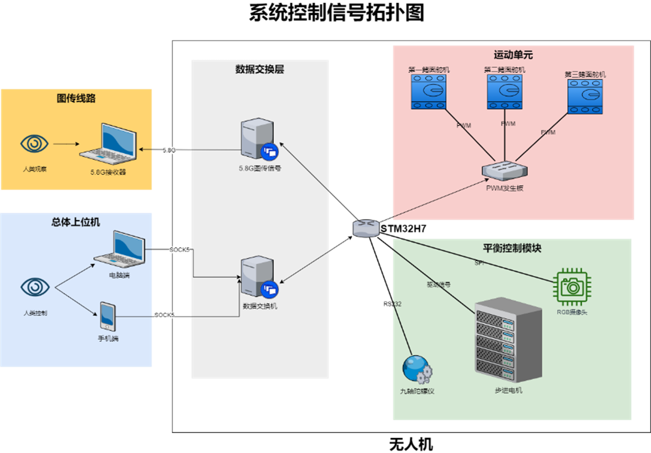
Figure 1: System Control Signal Topology Diagram
2.2 Design Proposal for the Underwater Robot’s Drive Unit
The main task of the drive unit is to adjust the shape of the fin surface to generate thrust. Based on the actual working characteristics, it can be divided into three main parts: the control system, the motion system, and the guidance system. The guidance system accomplishes the transmission function from the servo to the fin surface, and its structure is relatively simple, primarily consisting of rigid components connecting the servos. The control system controls the rate of rotation and steering angle of the servos by manipulating the frequency and duty cycle of PWM signals, thereby changing the shape of the fin surface. The motion system plays a driving role, and its internal control board ensures closed-loop control of the servos, preventing issues like large delays between multiple servos and differences between angle and speed control loops, thus making the force in the entire system more controllable.
Different design proposals for the drive unit can be obtained based on various criteria. Below, the servo is chosen as the drive unit based on the setup of the power source and the method of synchronous motion in the drive unit.
2.2.1 System Logic Power Supply Setup
The entire system requires power sources at 11.1VDC, 8.4VDC, and 5VDC. The 8.4VDC power supply is provided to the motors and lead screw sliders, while the 5VDC power supply is distributed to components such as the PWM generator, the underlying control board, and sensors. The power supply circuit comprises 8 UBEC batteries, 1 11.1V model aircraft battery, and various electrical components such as relays. The specific electrical diagram is shown in Figure 2.
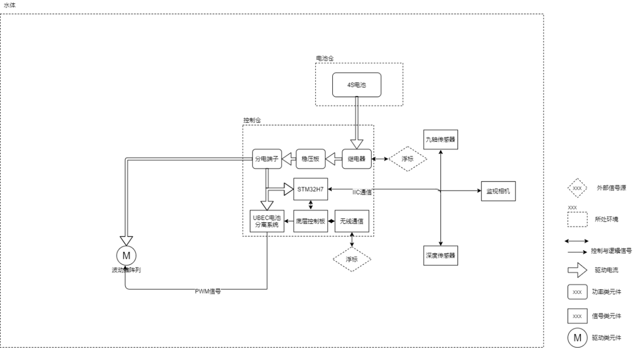
2.2 Power Supply Circuit Topology Diagram
To ensure experimental safety, a UBEC battery isolation system is incorporated into the power supply circuit mentioned above. It automatically disconnects all voltage leads from the battery when the driver encounters a malfunction. The UBEC system enables weak electrical control over strong electrical sources, self-locking, and protection functions.
2.2.2 Data Transmission and Reception Circuit Design and Implementation
The entire system operates within OPENMVH7 (STM32H7). The hardware components of the data transmission and reception circuit include a 5.8GHz video transmission module, a wireless module, and IPEX communication connectors.
Since the system supports the RS232 communication protocol, linear connections are established between the motor drivers and various sensors, allowing for a sampling frequency of up to 1KHz and precise synchronization with a time delay of less than 50μs. This fully satisfies the requirements of data exchange. The nine-axis sensor employs Kalman filtering and outputs data to the controller.
2.3 Overall Software System Design Proposal
In this design, the main controller needs to rapidly respond to interactive commands, perform high-speed numerical calculations, and execute program algorithms swiftly. As such, the controller places high demands on logic operations and real-time processing. After selection,
the OPENMVH7 main controller meets the system’s functional requirements. The specific parameters, post optimization, are as follows:
- The CPU employs STM32H7 with a maximum clock frequency of 480MHz and uses Python as the programming language, allowing remote firmware changes for the underwater vehicle.
- 64MB of RAM is selected for running memory.
The software system of OPENMV is based on C-language and designed with RTOS. The main controller can serve as an upper computer to send instructions or directly control devices and retrieve device status as a lower computer. The software system of the PWM signal generator board is relatively simple, mainly using loops and interrupts to obtain information and update servo control status. After installing MicroPython’s runtime kernel, the main controller becomes a real-time capable controller.
The software system of the drive unit mainly includes HMI interaction modules, closed-loop control algorithms, and motion control modules, among other parts. The interaction module is responsible for exchanging information between the machine and humans, including functions such as selecting operating modes, setting parameters, reading statuses, and monitoring errors. The closed-loop control algorithm is designed for different experimental modes, calculating the motion trajectory of the drive unit under different control strategies.
For ease of understanding, we refer to the OPENMV4H7 running MicroPython’s runtime kernel as the upper computer and the PWM signal generator board as the lower computer. Communication between the upper and lower computers is achieved via the RS232 interface.
2.4 Mechanical Design Principles and Implementation
2.4.1 Mechanical Design Principles
The propulsion mechanism of the wave-like fin is very complex, and its motion varies depending on different propulsion situations. However, during the steady-state swimming phase, it mainly exhibits a quasi-sinusoidal waveform. The three-wave fin structure in this project can use the dorsal fin in coordination with the nine-axis gyroscope module to rapidly reach the steady-state swimming phase of the vehicle. It utilizes the remaining two fins for kinematic calculation of the sinusoidal wave propulsion. This not only provides high-precision motion capabilities and rapid acceleration for even fins at low speeds but also makes control easier and more stable. Figure three depicts a schematic diagram of the propulsion structure.
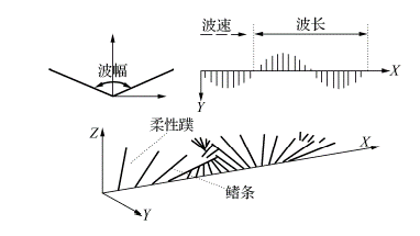
图3 Schematic Diagram of the Propulsion Structure
The maximum wave amplitude of this biomimetic wave-like fin device is 60°, and the servo is powered at 8.4V. The motion state of each adjacent fin of the fin surface can be described by the following equation:
\[\theta(n) = \theta_0(n) + \theta_{\text{max}}(n) [\omega t + e(n)]\]Where:
- θ(n) represents the current angular motion of the nth fin.
- θ₀(n) represents the initial angle of the nth fin.
- θmax(n) represents the maximum wave amplitude of the nth fin.
- ω is the angular frequency, ω = 2πf, where f is the dynamic wave frequency of the fin.
- e(n) is the phase difference relative to the first fin for the nth fin.
Equation (1) forms the basic model and basis for fin control in this project. Of course, previous research on MPF also involved studies on divergent waves, convergent waves, and so on. However, for steady-state aircraft, the quasi-sinusoidal wave model is the easiest to implement. This project, as a three-wave fin biomimetic aircraft, has a natural advantage in achieving steady-state flight with the odd fins coordinated with the threaded slider, enabling four degrees of freedom in balance control. Therefore, this article focuses on the analysis of motion under the quasi-sinusoidal model.
Due to the variability and complexity of fluids, the study of the propulsion mechanism of fish swimming is more complex than in other fields. With the introduction of fluid mechanics, aided by water tank experiments, fluid modeling, and numerical calculations, many different theories have emerged about the propulsion mechanism of fish. The following will present an approximate model of wave-like fin propulsion for design reference.
Figure 4 shows a schematic diagram of the wave-like fin’s propagation of fin surface waves to generate thrust during wave-like fin motion. In the figure, the solid line represents the fin surface wave at the current moment, and the dashed line represents the fin surface wave at the next moment. A, B, C, and D are four tiny elements of the fin surface. It can be observed that point A moves close to the X-axis due to fluid resistance, resulting in a resistance force f in the vertical direction of the fin surface, which can be decomposed into f_P in the X-direction (longitudinal axis) and f_L in the Y-direction (lateral axis). Similarly, points B, C, and D also experience similar f_P and f_L. Within one wavelength, integrating f_P and f_L for all tiny elements shows that f_L cancels each other out, while the magnitude of f_P is the sum of the absolute values of f_P for all tiny elements and its direction is opposite to the direction of wave propagation. Thus, within the entire wavelength, the net force acting on the fin surface is a propulsive force opposite to the direction of wave propagation, and all elements contribute to this force.
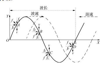
Figure 4: Schematic Diagram of Thrust Generation
2.4.2 Mechanical Design and Assembly
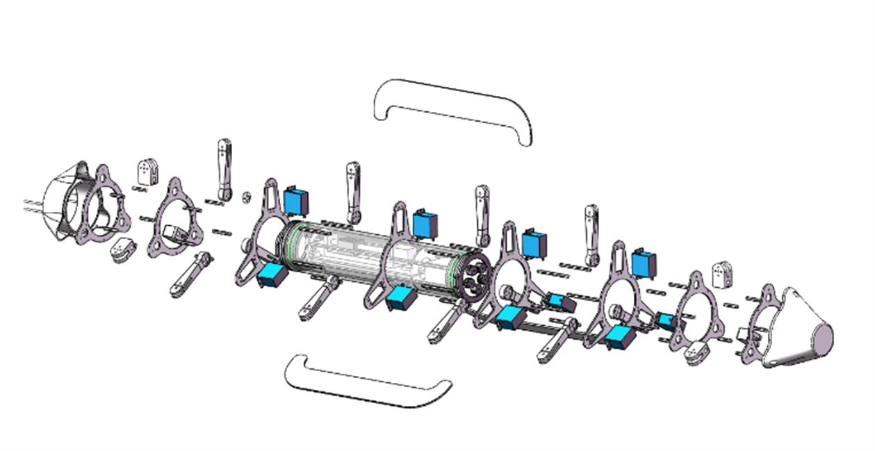
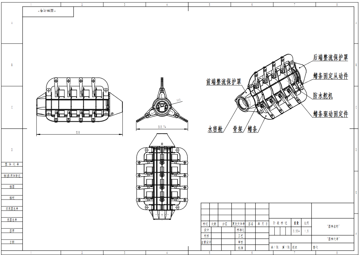
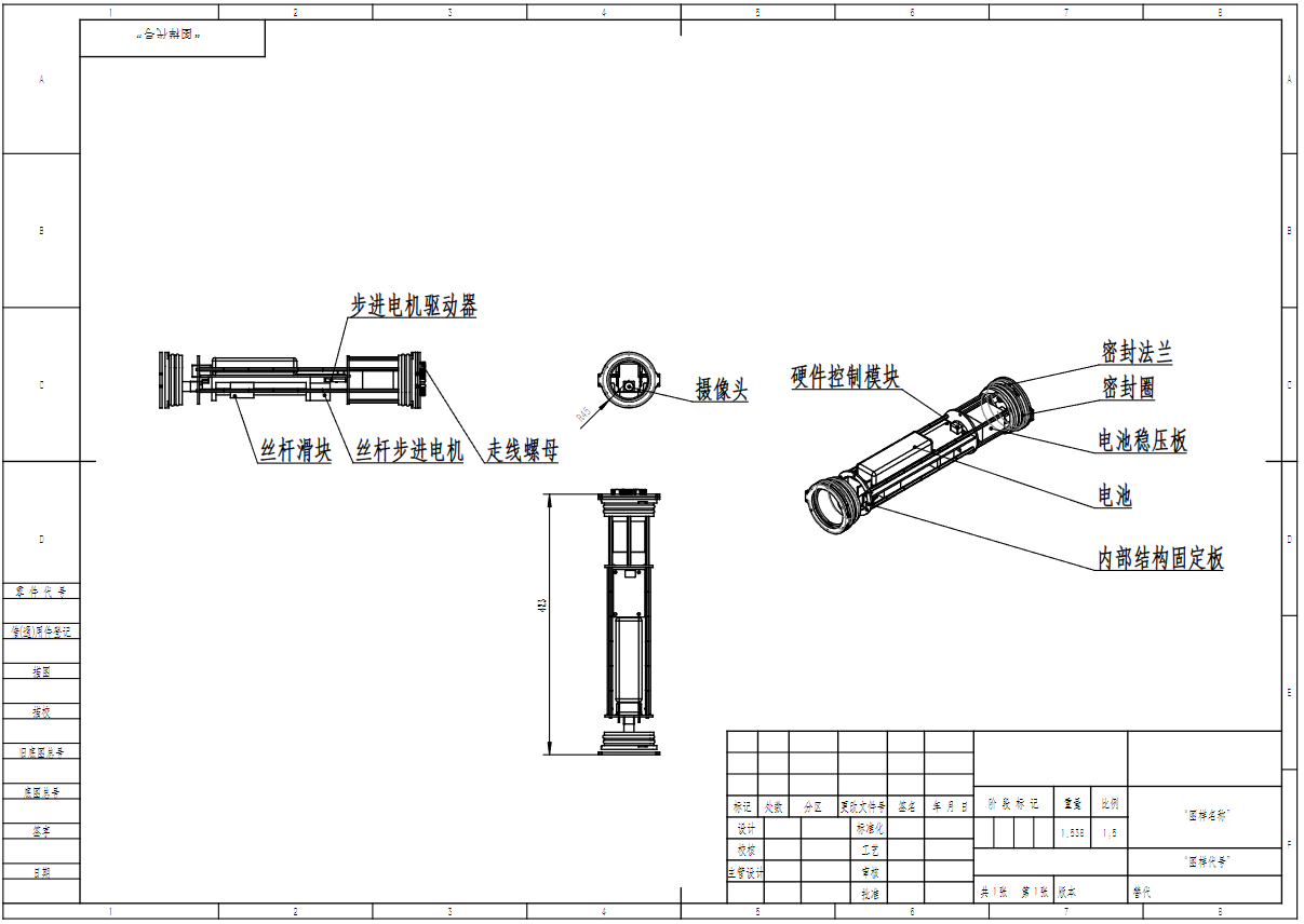
Figure 5: Exploded Design
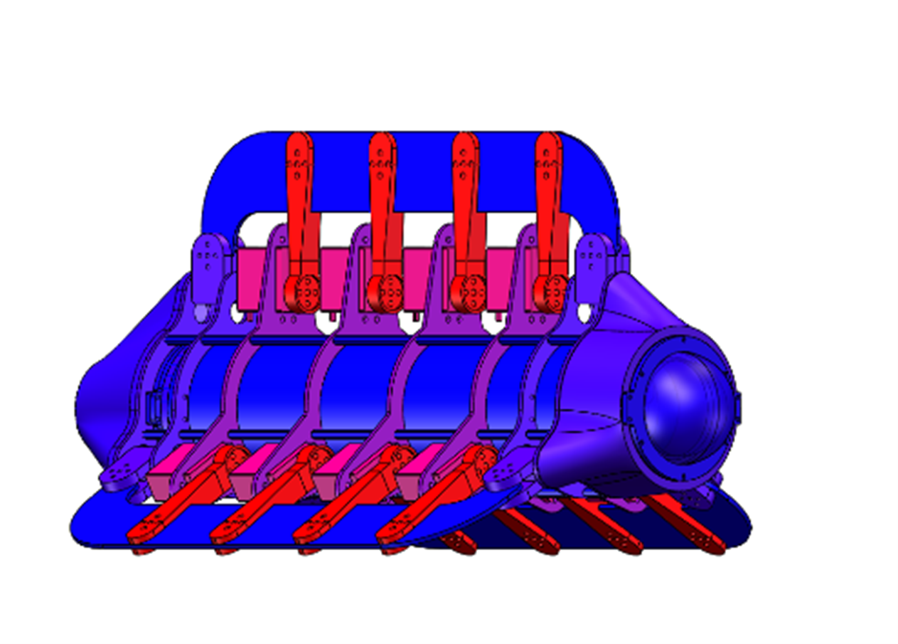
Figure 6: Assembly Design
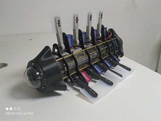
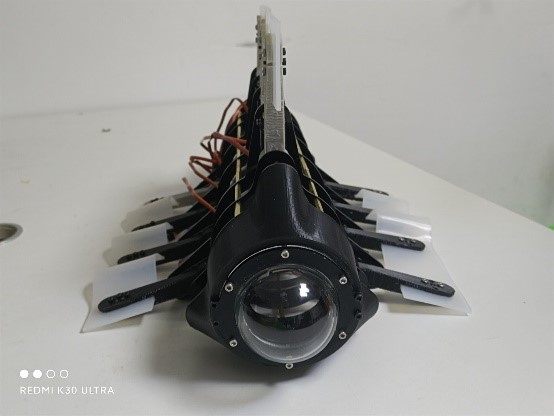
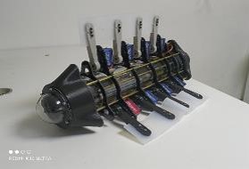
Figure 7: Physical Assembly
Chapter 3: Experimental Data
3.1 Self-Stabilization Experiment
Figure 8 shows the three-axis acceleration data for self-stabilization obtained by applying Kalman filtering to the nine-axis data and then using a fuzzy PID control algorithm. This demonstrates that combining the nine-axis sensor data with a closed-loop self-stabilization algorithm is highly suitable for maintaining stability in underwater robots.
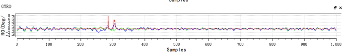
Figure 8: Self-Stabilization with Nine-Axis Sensor Data and Kalman Filter
Figure 9 displays the three-axis acceleration data for self-stabilization after applying window filtering to the nine-axis data and using a linear control algorithm.
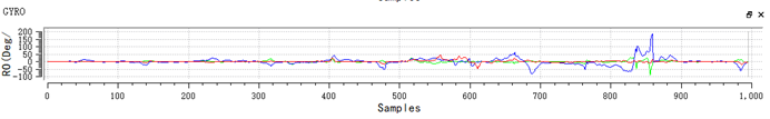
Figure 9: Self-Stabilization with Nine-Axis Sensor Data and Window Filtering
Figure 10 illustrates the deviation between the expected waveform and the actual waveform of the MPF oscillating fin underwater.
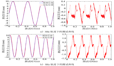
Figure10 Matching Degree of MPF Waveforms
Chapter 4: References
[1] Wang Tianmiao, Yang Xingbang, Liang Jianhong. Review of Biomimetic Autonomous Underwater Robots with Central Fins/Paired Fins Propulsion Modes [J]. Robotics, 2013, 35(3).
[2] Wang Guangming. Theoretical and Experimental Study on Biomimetic Flexible Long Fin Oscillatory Propulsion in Fish [D]. Changsha: Graduate School of National University of Defense Technology, 2007.
[3] Anderson J M, Streitlien K, Barrett D S, et al. Oscillating foils of high propulsive efficiency. JOURNAL OF FLUID MECHANICS, 1998, 360(360): 41-72.
[4] Triantafyllou G S, Triantafyllou M S, Grosenbaugh M A. Optimal Thrust Development in Oscillating Foils with Application to Fish Propulsion. Journal of Fluids & Structures, 1993, 7(2): 205-224.