Model Preview
This model has a total size of 3.1 MB. It may take some time to load, so please be patient!
I. Background
The continuous development of military and maritime strategies in various countries aims to secure technological and military advantages in marine and coastal areas. China, with its vast marine geographical environment, places great importance on the development of maritime strategy. As a platform for marine exploration and a carrier for modern underwater weapons, the technological research of underwater robots is of great significance. Due to the complexity of the underwater environment, the adaptability and compatibility of robot systems with the environment are critical. After centuries of evolution, fish have developed highly efficient swimming capabilities, adaptability to specific aquatic environments, and a high level of intelligence. This has inspired research on propulsion principles, control algorithms, and action strategies for underwater robots based on biomimetic principles and relevant environmental information, making it a major focus of advanced international underwater robot technology research.
The excellent swimming methods of fish provide inspiration for improving the propulsion performance and adaptability of underwater robot propulsion systems. Research on fish-like propulsion modes and biomimetic propulsion technology has become a hot topic in the field of underwater propulsion research. The development of biomimetic technology, computer technology, control technology, and material technology provides strong support for research on the control theory and methods, motion principles, system composition and implementation, control algorithms, and other aspects of fish-like underwater robots. Research on new fish-like underwater propulsion systems has become a hot spot in current research on underwater robots, and a series of achievements have been made.
The development of a cross-medium flying vehicle is of great significance. Its flexible and rapid advantages can be used for various applications, from wave sampling during floods to environmental monitoring in aquatic environments and responses to aquatic disasters. Integrating multi-terrain mobility into one system can achieve various important applications in oceanography, reservoir management, and agriculture. Current methods for water monitoring are time-consuming and resource-intensive, especially in remote or hazardous marine environments, such as during nuclear accidents, in the Arctic, or in flood-prone areas. Cross-medium flying vehicles can provide samples to base stations over a wide area and react more quickly than single-domain water, air, or land systems. In civil applications, it will be possible to play a significant role in rapid search for aircraft accidents at sea and rapid rescue of accident victims. For long-distance target detection, the cross-medium flying vehicle can first reach the target area in flight in a short time, and then switch to underwater for close-range observation, fully utilizing the advantages of the cross-medium flying vehicle.
The difficulty of this project lies in the significant difference in environmental external forces and corresponding dynamic responses when the amphibious vehicle operates in two completely different environmental media: air and water. The design requirements often conflict with each other. The issue of high power density has always restricted the application of robots in practical tasks, especially in small-scale applications. In addition, because of the additional resistance and the mass of the water brought by the cross-medium, it is necessary to accelerate quickly to the speed required for flight. The transition from the water surface to flight is one of the most power-consuming processes. To address these issues, this project proposes a cross-medium propulsion system that generates combustible gas using solid reactants. This provides a promising solution for future robotic technology in cross-medium propulsion.
II. Innovations
-
Use of Solid Fuel: While existing cross-medium vehicles have used propellers or gas fuels to achieve cross-medium capabilities, research on the use of solid fuels is still limited. Solid fuels are stable and suitable for long-term storage, making them important for expanding cross-medium vehicle research.
-
No Direct Use of Gas Working Fluid for Propulsion: The project achieves self-sealing after ignition using a mechanical self-filling water device. By using jet water as the driving method, it achieves a higher energy utilization rate.
-
Lightweight Propulsion System Design: The project designs a lightweight propulsion system capable of flight through water jet propulsion. This system can withstand high pressure and aquatic environments, and handle tasks such as calcium carbide reactions, fuel ignition, high-pressure operations, wireless communication, and power management.
III. System Design Principles
3.1 Chemical Reaction
A large amount of fuel gas can be stored compactly as a liquid under high pressure. However, this requires storage and regulation systems capable of withstanding tremendous pressure, which adds complexity, danger, and weight to the components. If combustible fuel is generated from the reaction of two independent stable components, high pressure can be avoided, greatly simplifying the fuel storage and distribution system. The use of solid compounds for gas storage is common in many applications, such as the use of sodium azide (NaN3) to decompose and release nitrogen gas (N2) for inflating automobile airbags or using solid alkali metal hydrides to store hydrogen in the fuel cell industry.
More relevant to underwater propulsion is the use of lithium hydride for torpedo propulsion systems or the use of solid reactants for buoyancy control in naval research. Additionally, using water as a reactant is a good choice for aquatic robots because it allows them to reduce system mass by utilizing their environment.
We have developed a fuel and ignition system that draws water droplets from the surrounding water and injects them into a small container filled with calcium carbide powder. Counting the water droplets in this way can provide a good estimate of the amount of acetylene produced. Calcium carbide and water undergo the following exothermic reaction:
\[\mathrm{CaC}_2+2 \mathrm{H}_2 \mathrm{O} \rightarrow \mathrm{Ca}(\mathrm{OH})_2+\mathrm{C}_2 \mathrm{H}_2 \uparrow\]Producing acetylene gas (C2H2) that escapes into the combustion chamber, where it mixes with the air. During this process, 0.3 mg of acetylene is generated per milligram, with a purity of 75%. Finally, the gas mixture is ignited by an electric arc, resulting in combustion:
\[2 \mathrm{C}_2 \mathrm{H}_2+5 \mathrm{O}_2 \rightarrow 4 \mathrm{CO}_2+2 \mathrm{H}_2 \mathrm{O}\]This reaction is highly exothermic, rapidly raising the temperature and pressure inside the reaction chamber, forcing water to flow out of the combustion chamber, generating the required thrust.
3.2 Jet-Gliding Physics
We have developed an analytical physical model to delve into the pressure evolution and flight trajectory, as well as to determine various robot parameters and their impact on robot performance. Pressure-driven locomotion presents two primary physical issues. First, the external view of the robot accounts for the flight trajectory based on forces on the robot. Second, internal considerations enable us to calculate pressure evolution and thrust. Due to the coupling of the internal and external, both sets of equations must be solved simultaneously. This coupling arises from the effect of the robot’s acceleration on the water in the chamber, which affects the generated thrust. The following equation is applied to our system:
\[\Sigma \vec{F}=\overrightarrow{\mathrm{Th}}-\vec{W}-\vec{D}-\vec{L}\]In this step, the robot is considered a point mass moving in two dimensions (2D). Th represents jet thrust, W represents weight, D is drag, and L is lift. The thrust is given by the Euler flow equation applied from the high-pressure air region (interface) to the chamber at the nozzle.
\[\int_{\text {nozzle }}^{\text {interface }} \frac{\partial u}{\partial t} \mathrm{ds}+\frac{\Delta P}{\rho_w}+\frac{1}{2}\left(u_{\text {nozzle }}^2-u_{\text {interface }}^2\right)=0\]Assuming that the pressure ΔP follows adiabatic expansion, the initial pressure Pinit is given by the chemical stoichiometric energy conversion. ρw is the water density at 20°C. The point velocity u in the chamber is always defined as:
\[u(z, r, t)=\frac{\mathrm{dh}}{\mathrm{dt}}\left(\frac{\Omega(h)}{\Omega_{\text {nozzle }}}\right) f\left(\frac{r}{R(z)}\right)\]Velocity is a function of water level height h, interface area Ω(h), distance to the axis r, and chamber size R(z). The most important overall performance metric for the robot is the distance traveled per jet cycle, which can maximize the usefulness of its mission. To maximize jump-glide performance, we iterated the above comprehensive flight analysis model, varying nozzle diameter, water volume fraction, and launch angle for optimizing the travel distance. The nozzle diameter was 2.8 cm, resulting in a final total volume of 491 milliliters with a water content of 40%, equivalent to 196.4 milliliters. Finally, through analysis, the optimal launch angle for the maximum flight distance was found to be 47°, and the robot’s mass distribution was altered to float at the set angle. During the propulsion phase, a 3D Computational Fluid Dynamics (CFD) study of the flow inside the chamber was conducted to validate the results obtained in the physical model and understand the flow behavior in 3D. This ensures that the analysis model represents conditions as realistically as possible before manufacturing the robot.
Four. Technical Roadmap
4.1 Proposal of the Cross-Medium Propulsion System
Considering the high power consumption and limitations of electromechanical drive for taking off from water, as well as the complexity of the external environment, the project’s challenge lies in choosing a suitable cross-medium propulsion technology.
We propose using combustible gas generated from solid reactants as the power source for cross-medium jumps. Specifically, we will react powdered carbide with available environmental water to generate combustible acetylene gas. A peristaltic pump will be used to draw water from natural bodies of water, and the generated acetylene gas will be transported to the reaction chamber through a conduit, where it will be ignited. This will allow the robot to jump out of the water and quickly reach flying speed using water as the working fluid.
We have conducted numerical modeling for the combustion, jetting, and gliding phases separately, and compared the results with experimental data. According to calculations, 0.5 grams of carbide can propel a 360-gram robot to fly 26 meters.
To withstand the pressure generated by acetylene explosions, the robot body is made of short-cut carbon fiber and epoxy resin through processes such as impregnation and drying. Compared to traditional composite materials, it has higher strength and rigidity, as well as lighter weight, greater heat resistance, and better corrosion resistance.
4.2 Mechanical Design
1. Design Drawings and Real-World Images
Top View:
 Left View:
 Front View:
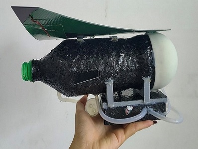
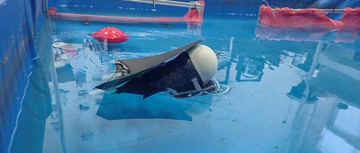
 Real-World Images:
The overall mechanical structure of this project is briefly shown in the above figures. The main parts of the mechanism are the main body 11, fuel tanks 1 and 3 mounted on the main body 1, and calcium carbide is placed inside. It reacts with water to generate acetylene gas, which is transported to the intake and ignition device 10 through the gas delivery tube (not shown), allowing the gas to enter the main body 11. When the gas reaches a certain concentration, the ignition device 10 generates an electric spark to ignite the gas. Due to the presence of the one-way valve 7, water can enter the main body 11, causing the overall structure to tilt upwards. When the internal gas ignites, the huge pressure prevents the one-way valve 7 from opening, causing the pressure generated by the gas to be expelled from the tail of the main body 11, creating thrust and propelling the entire mechanical structure out of the water.
2. Mechanical Design Iteration Process
3. Hydrodynamic Self-Stabilization Principle
An air needle is installed at the head of the combustion chamber of the aircraft to connect the internal air pressure of the combustion chamber with the external atmospheric pressure. When the aircraft falls into the water, water flows in through the rear opening of the combustion chamber. As the water level in the combustion chamber rises, the compressed air inside the chamber is expelled through the air needle. When the water level submerges the air needle hole, the internal air pressure of the combustion chamber acts in conjunction with the water pressure to balance the external atmospheric pressure. At this point, the water level no longer rises, and the volume of the aircraft submerged in the water remains unchanged. In the ideal state, the buoyancy and center of gravity reach a stable state, and the buoyant force and gravity are equal and opposite, allowing the aircraft to achieve stable buoyancy.
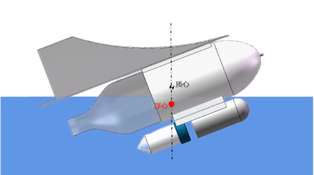
4. Aircraft Center of Mass
Based on the actual situation of each part of the aircraft, material properties are set, and the mass property evaluation function in SOLIDWORKS software is used to obtain a total mass of approximately 524 grams for the entire aircraft. The overall center of mass is located near the middle of the aircraft. Therefore, in the actual process of water-to-air gliding, a favorable center of mass position can be used for angle correction control, ensuring the stability of the aircraft’s cross-medium motion and gliding.
5. Fluid Simulation
A simulation was conducted for different launch angles using the Flow Simulation simulation function in SOLIDWORKS. A turbulent one-way flow model was used, and the simulation was solved using the Navier-Stokes equation.
\[\begin{gathered} \rho(u \cdot \nabla) u=\nabla \cdot[-p I+K]+F \\ \rho \nabla \cdot(u)=0 \\ K=\left(\mu+\mu_T\right)\left(\nabla u+(\nabla u)^T\right) \\ \rho(u \cdot \nabla) k=\nabla \cdot\left[\left(\mu+\frac{\mu_T}{\sigma_k}\right) \nabla k\right]+P_k-\rho \varepsilon \\ \rho(u \cdot \nabla) \varepsilon=\nabla \cdot\left[\left(\mu+\frac{\mu_T}{\sigma_{\varepsilon}}\right) \nabla \varepsilon\right]+C_{z 1} \frac{\varepsilon}{k} P_k-C_{z 2} \rho \frac{\varepsilon^2}{k} f_r\left(\rho, \mu, k, \varepsilon, l_w\right), \varepsilon=\sigma p \\ \nabla G \cdot \nabla G+\sigma_w G(\nabla \cdot \nabla G)=\left(1+2 \sigma_w\right) G^4, \ell_w=\frac{l}{G}-\frac{\ell_{r e f}}{2} \\ \mu_T=\rho C_\mu \frac{k^2}{\varepsilon} f_\mu\left(\rho, \mu, k, \varepsilon, \ell_w\right) \\ P_k=\mu_T\left[\nabla u:\left(\nabla u+(\nabla u)^T\right)\right] \end{gathered}\]The simulation results at launch angles of 30°, 35°, 40°, and 45° are shown in the figure below.
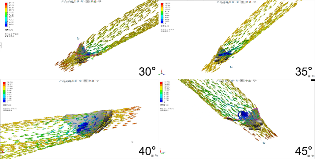
From the simulation, it can be observed that vortexes appear on the back of the wing at launch angles of 35° and above, which reduces the adhesion of air to the wing surface, leading to stall. At launch angles around 30°, there are no vortexes on the back of the wing, resulting in effective adhesion effects. Therefore, sufficient pressure difference can be formed between the upper surface of the wing and the lower surface of the aircraft, generating enough lift to complete the gliding action.
4.3 Overall Implementation Process of the Cross-Medium Craft
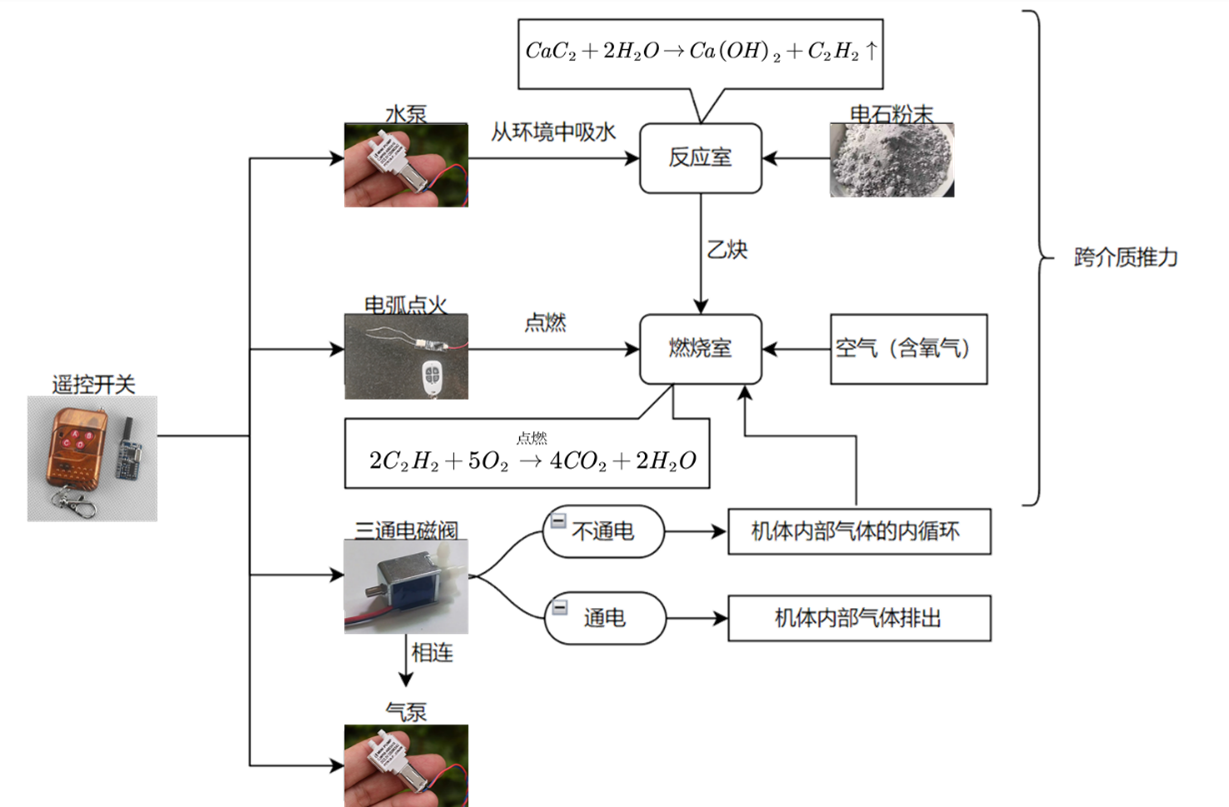
System Framework: In this project, three remote control switches are used to control the peristaltic pump to draw water from the environment, ignite the arc igniter, and switch the three-way solenoid valve. The first two components are used for the reaction between calcium carbide and water, as well as ignition of acetylene, resulting in thrust. The three-way solenoid valve is connected to the air pump, and in its normally open state, it maintains internal gas circulation within the craft to prevent insufficient contact between generated acetylene and oxygen. After switching, it is used to expel the internal gas, increasing overall density for descent. To rise, the water pump is activated again, and the reaction between calcium carbide and water generates acetylene, expelling the internal water and reducing overall density, achieving buoyancy. At this point, the internal gas is entirely acetylene, devoid of oxygen, making it impossible for the second-stage reaction. Briefly activating the three-way solenoid valve again, and since the craft is already floating on the water surface, it equalizes the internal and external gas pressures through the gas needle. Some air (containing oxygen) enters the craft through the gas needle. The solenoid valve is closed again, continuing internal circulation to mix air and acetylene. This enables ignition for the second-stage cross-medium transition. This process is repeated until the calcium carbide in the reaction chamber is exhausted.
Power Supply Scheme:
5. Supportive Theories and Technologies for the Project
5.1 Variable Geometry Technology for Aircraft
Due to the significant differences in physical properties such as density and viscosity between water and air, the movement characteristics of an aircraft in these two media are drastically different. For example, wing configurations providing lift during aerial flight create significant drag when navigating through water, affecting pitch control. Therefore, the use of variable geometry technology to adaptively change the configuration during different flight phases is crucial for efficient and stable cross-medium flight. Variable geometry technology for cross-medium flight focuses on increasing lift and reducing drag during aerial flight phases, improving pressure resistance during underwater phases, and ensuring strength and stability during medium transitions. Existing solutions include small-scale wing deformations such as variable wing curvature, thickness, and twist. Current methods, however, face challenges such as high torque requirements for hinge joints and complex control.
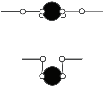
(a) lateral folding wings
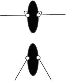
(b) variable-sweep wings
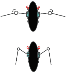
(c) biomimetic flapping wings
5.2 Cross-Medium Fluid Dynamics Analysis
The main challenge in the fluid dynamics analysis of cross-medium variable aircraft lies in analyzing the unsteady flow characteristics during the variable and medium-transition processes. The analysis of unsteady flow characteristics and the modeling of aircraft dynamics are achieved through theoretical analysis, numerical simulation, or physical experiments. Medium transition involves complex flow phenomena, typical of gas-liquid two-phase interference motion. This process is accompanied by air cushion effects, gas-liquid coupling, jet phenomena, as well as the growth, development, and collapse of water-entry air pockets. Moreover, the effects of waves introduce significant unsteady and nonlinear characteristics, posing challenges in comprehensively understanding the fluid dynamic behaviors of cross-medium variable aircraft. Furthermore, the rapidly changing flow environment demands highly responsive and robust control of the aircraft.
5.3 Cross-Medium Combined Propulsion
Traditional aircraft typically use air propellers, air jet engines, or rocket engines for propulsion. Air propellers have a relatively high weight and low propulsion efficiency. Air jet engines require air intake and are unable to operate underwater. Rocket engines generally have short operational durations, low specific impulses, and inadequate long-range flight capabilities. Traditional underwater vehicles use underwater propellers, pump jet propulsors, or water jet propulsion systems. These underwater propulsion methods often have configurations distinct from their airborne counterparts and are not easily adaptable. The integration of both systems for cross-medium aircraft presents challenges in spatial layout and increased structural weight. Therefore, there is a pressing need to research integrated cross-medium combined propulsion systems. Currently, bio-inspired flapping wing propulsion systems have been tested on low-speed cross-medium aircraft. However, for high-speed cross-medium maneuvers, further research and development of integrated cross-medium combined propulsion systems, based on high-energy-density energy sources such as hydrogen fuel cells, are required.
5.4 Aircraft Decision and Control
To achieve stable flight/navigational control throughout the stages of takeoff, cruising, medium transition between water and air, submersion, silent lurking, breakthrough, and attack, cross-medium variable aircraft require online intelligent decision-making based on mission requirements and current environments, enabling adaptive configuration changes. Furthermore, the complex and dynamically changing navigational environment of cross-medium variable aircraft, along with significant differences in configuration between different mission stages, necessitates the establishment of multi-rigid body or even multi-flexible body dynamic models. These provide the basis for developing a rapid-response and robust control system, ensuring stable control of the aircraft in situations involving rapid deformation and large parameter variations.
6. Application Prospects
-
Civil Applications: Cross-medium craft with the advantages of structural stability, low cost, adaptability to a wide range of terrains, and a large exploration range have extensive applications. Due to their excellent mechanical structure, cross-medium craft are well-suited for performing detection tasks in various complex environments. They can be used for applications such as ocean exploration, water quality testing, underwater biological research, and underwater substance sampling.
-
Military Applications: As platforms for ocean exploration and carriers of modern underwater weapons, underwater robots have shifted their technical focus from cruise and speed performance during the Cold War to maneuverability and autonomy after the Cold War. Advanced underwater robot technology and its applications in extreme environments have become the focus of research and development in various countries. Cross-medium craft have great potential in military applications such as underwater reconnaissance, sonar sampling, and concealed strikes against enemy military facilities. It can be envisaged that, in the near future, cross-medium craft will become a third category of vehicles independent of both airborne and underwater craft.
7. Future Work Plan
-
Enhance the underwater mobility of robots using variable geometry technology. For example, design a spiny mechanism to drive wing deployment automatically when submerged, maintaining a streamlined shape, and retracting wings during aerial and cross-medium flight to ensure stability.
-
Implement cluster algorithms to achieve cooperative work with multiple AUVs, expanding their application scenarios. Methods such as the average moving vector method and potential field method can be deployed.
8. References Used in the Design Process
[1] Tong Zhaofeng, Wei Zhiyang, Meng Yanqiu. Wave-making effect of a vertical two-dimensional numerical wave flume based on FLUENT. Water Transport Engineering. 2020, (3), 13~20.
[2] Luo Yuchuan, Huang Zhengui, Gao Jianguo, et al. Experimental study on low-speed oblique entry of conical-nose projectiles into water. Explosion and Impact. 2019, (11), 77-84. doi:10.11883/bzycj-2018-0498.
[3] Lu Zhonglei, Sun Tiezhi, Wei Yingjie, et al. Experimental study on the motion characteristics of an open cavity shell tilting into water. Acta Mechanica Sinica. 2018, (2), 263-273.
[4] He Zhaoxiong, Zheng Zhenshan, Ma Dongli, et al. The development history and inspiration of foreign cross-medium aircraft. Ship Science and Technology. 2016, (5), 152-157. doi:10.3404/j.issn.1672-7619.2016.05.032.
[5] Yang Haiyan, Lin Shuyu, Lin Ke. Dynamic characteristics of aircraft in air and underwater flight. Journal of South China University of Technology (Natural Science Edition). 2015, (11), 127-132, 144.
[6] Xing Wenzhong, Jiang Zhen. Configuration design and aerohydrodynamic analysis of UAV. Journal of Projectiles, Rockets, Missiles and Guidance. 2015, (4), 113-117.
[7] Lin Ke, Feng Jinfu, Zhang Xiaoqiang, et al. Research on the hydrodynamic characteristics of a lifting-type submersible aircraft. Ship Science and Technology. 2014, (9), 94-97, 105.
[8] Yang Xingbang, Liang Jianhong, Wen Li, et al. Research status of cross-medium amphibious unmanned aerial vehicles. Robot. 2018, (1), 102-114. doi:10.13973/j.cnki.robot.170241.
[9] Hou Zhao, Sun Tiezhi, Zhang Guiyong, et al. Experimental study and six-degree-of-freedom numerical calculation of inclined entry of rotating body into water and air bubbles. Aerospace System Engineering. 2017, (4), 38~45.
[10] Liao Baoquan, Feng Jinfu, Qi Duo, et al. Research on aerohydrodynamic characteristics of a new cross-medium aircraft based on FLUENT. Numerical Calculation and Computer Applications. 2016, (4), 265-272.
Appendix - Cost Breakdown Table
| Cost Item | Quantity | Amount (CNY) |
|---|---|---|
| 6mm Chopped Carbon Fiber | 1 kg | 150 |
| Twill Carbon Fiber Prepreg Fabric | 1 m² | 100 |
| Propellers | 4 pairs | 50 |
| Epoxy Resin Potting Adhesive | 3 kg | 100 |
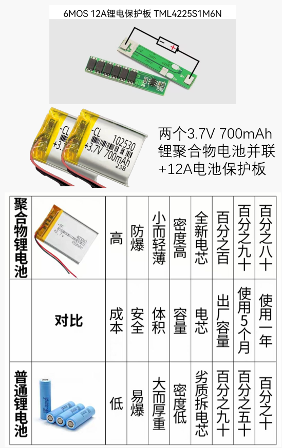
| 18650 Li-ion Batteries, 3.7V 700mAh Li-Po Batteries | Various | 200 |
| Ignition Modules | 4 | 200 |
| Receivers, Remote Controllers | 4 pairs | 200 |
| Hollow-Cup Motors, Mini Diaphragm Pumps | 4 | 100 |
| Bluetooth Remote Motor Drive Module | 2 | 100 |
| Waterproof Spray Paint | 50 ml | 50 |
| Industrial Drying Oven | 1 | 500 |
| Calcium Carbide | 100 g | 10 |
| Other Parts (DuPont Wires, Enamel-coated Wire, Connector Wires, Battery Protection Boards, Charging Boards, Vent Boards, Molds) | Various | 300 |
| Total | 2060 |