
Model Preview
This model has a total size of 55 MB, and it may take some time to load. Please be patient!
Abstract
With the development of robotics technology, robots are becoming capable of performing various functions, and their intelligence is constantly improving. Robots are widely used in various fields of people’s lives. Football is a popular sport worldwide, and robot soccer has a high level of entertainment value. It also contributes to technological innovation. In the development of robot soccer, the focus is on the robot’s ability to acquire and process information, as well as its ability to control, which serves as the basis for the development of robot soccer capable of handling complex tasks and variable working environments.
This project involves the design and production of a fully autonomous wheeled football robot, capable of engaging in ball challenges, automatically recognizing and picking up balls, and participating in cooperative competitions. It utilizes robotics technology to enable intelligent football matches. The applied technologies include vision design using panoramic cameras, motion control using evenly distributed omnidirectional wheels, hardware design incorporating electromagnetic ejection systems and control methods, as well as path planning and offensive-defensive strategies.
This project effectively enhances the mobility and stability of football robots, improves kicking accuracy and shooting range, and has significant innovative significance for the design and improvement of football robots. It can effectively achieve fully autonomous 1vs1 wheeled football robot competitions.
1. Introduction
1.1 Project Background
With the development of robotics technology, the intelligence of robots is constantly improving. Robot soccer matches not only have a high level of entertainment value but also contribute to technological innovation.
To achieve fully autonomous 1vs1 robot soccer competitions, robots need to have skills such as ball kicking, including ball recognition, ball chasing, ball possession, and shooting abilities. The idea of robots playing soccer was first proposed by Professor Mackworth of the University of British Columbia, Canada, in his book “On Seeing Robot” in 1992. At the same time, some Japanese researchers were also working on using robots to play soccer to promote scientific and technological development. In June 1993, during the Second Micro Robot Soccer Competition (MiroSot97) held at KAIST, South Korea, the Federation of International Robot-soccer Association (FIRA) was established. Since then, FIRA has organized the Robot World Cup (RoboCup) every year worldwide, along with the FIRA Congress for participants to exchange their experiences and technologies in robot soccer research.
1.2 Current Status of Robot Soccer in China
Robot soccer research in China started relatively late.
In 1997, Northeastern University was the first to establish a FIRA robot soccer team. In 1998, the University of Science and Technology of China formed the first RoboCup soccer team in China. In 2006, the University of Science and Technology of China’s team won one championship, one runner-up, and one fifth place in RoboCup. In 2010, Beijing Information Science and Technology University won the RoboCup wheeled championship and successfully defended the title in 2011. In 2013, Zhejiang University’s ZJUNlict team won the RoboCup small-size league championship, while Nanjing University of Posts and Telecommunications’ Apollo3D team won the RoboCup 3D simulation league championship. Beijing Information Science and Technology University’s robot soccer team Water once again won the RoboCup wheeled championship in 2013, achieving the remarkable feat of winning three out of four championships. In 2014, the University of Science and Technology of China’s Blue Eagle team won the RoboCup@Home championship. In 2015, Beijing Information Science and Technology University’s Water team again won the RoboCup wheeled championship. In 2018, Zhejiang University’s ZJUNlict team won the RoboCup small-size league championship.
RoboCup not only has the World Cup but also domestic competitions. Domestic competitions started in 1999 and have been held annually since then. Starting in 2002, the Robotics Competition Committee of the Chinese Association for Artificial Intelligence began to organize and unify robot soccer competitions, including both RoboCup and FIRA projects, further promoting and facilitating domestic robot soccer competition activities.
1.3 Introduction to Wheeled Soccer Robots
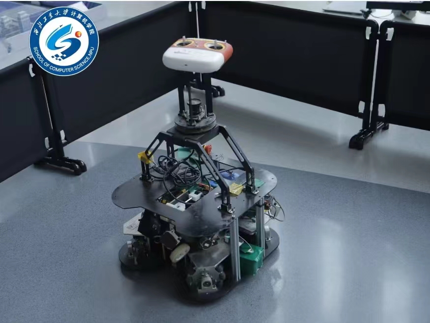
The ground projection of wheeled soccer robots should be larger than 30cm × 30cm and smaller than 50cm × 50cm. The height of the robot should be no less than 40cm and no more than 80cm. The robot’s weight should not exceed 40kg. The matches are played on a field measuring 12 meters in length and 8 meters in width, using a standard FIFA size 5 soccer ball.
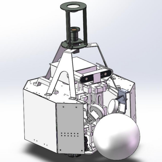
Figure 1.1 Wheeled Soccer Robot
A common structure of wheeled soccer robots is shown in Figure 1.1. It consists of several subsystems:
- The bottom-level mobility platform system, including omnidirectional wheels, motors, drivers, and controllers, among others. Typically, it has a three-wheel or four-wheel structure, driven by motors to achieve omnidirectional motion or rotation, as shown in Figure 1.2.
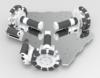
Figure 1.2 Bottom-Level Mobility Platform
- The ejection system, including a kicking rod, kicking plate, cylinder, spring, or electromagnetic coil, among others. It is usually pneumatic, spring-based, or electromagnetic, allowing the robot to perform kicking actions, as shown in Figure 1.3.
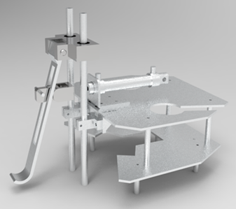
Figure 1.3 Kicking Structure
- The ball possession system, including a ball-holding motor, friction wheel, guiding wheel, among others. Typically, it rotates the friction wheel via a motor, applying force to the soccer ball in the direction of the robot, keeping the ball in front of the robot and allowing the robot to move the ball, as shown in Figure 1.4.
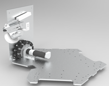
Figure 1.4 Ball Possession Structure
- The perception system, including panoramic cameras, front cameras, and various sensors, among others. This allows the robot to recognize moving targets and objects of different colors, as well as obtain its own position and status. The most important component is the panoramic camera, as shown in Figure 1.5.
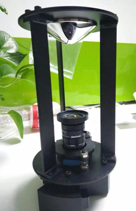
Figure 1.5 Panoramic Camera
- The decision-making system: The decision-making system consists of an upper-level computer and a lower-level computer. The lower-level computer is responsible for controlling the bottom-level mobility platform system, ball possession system, and ejection system, as well as collecting sensor data, among others. The upper-level computer is responsible for image recognition and processing, issuing motion commands, assigning robot roles, and strategy formulation, among other tasks. The upper and lower levels work together to enable the robot to perform relevant actions on the field.
2. Analysis of Advanced Technologies in Wheeled Soccer Robots
From the perspective of the rules, when designing soccer robots, it is required that soccer robots must be able to achieve fully autonomous movement, dribbling, passing, and shooting. In this regard, the top soccer robot teams around the world are constantly innovating. Let’s analyze the advanced technologies in this field:
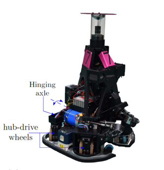
Figure 2.1 TUE Soccer Robot
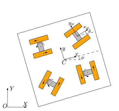
Figure 2.2 Four-Wheel Same-Direction Mobility Chassis
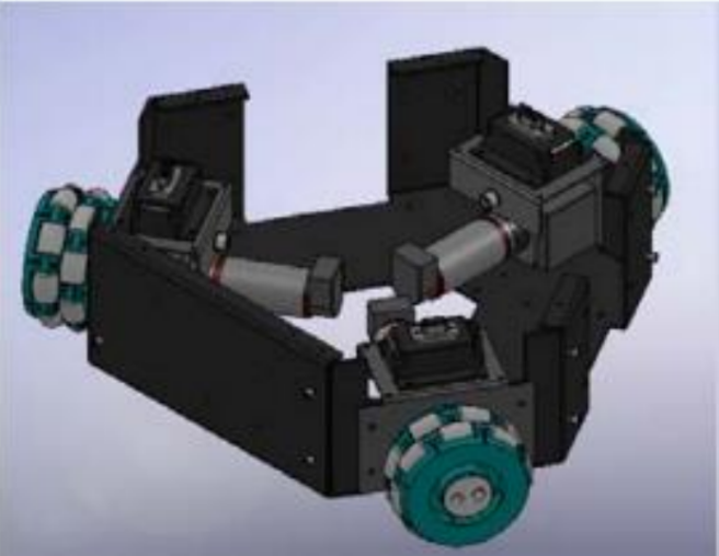
Figure 2.3 Three-Wheel Omnidirectional Mobility Chassis
1.3 Mechanical Structure
The ball possession mechanism of soccer robots must have strong ball-attraction capability and damping ability to reduce errors during ball possession. Additionally, the ball possession mechanism should be equipped with angle sensors or linear displacement sensors for feedback and adjustments. For example, TUE team uses direct maxon motors to drive friction wheels for ball attraction, as shown in Figure 2.3. The WATER team achieves ball attraction by synchronously driving the friction wheels with belts or using Mecanum wheels, both of which firmly hold the ball and perform related functions.
The kicking mechanism of soccer robots must deliver powerful kicking ability and precise control over the kicking height. Currently, international top teams commonly use electromagnetic ejection as the main power source for kicking, as it provides greater kicking force and faster energy accumulation. As for adjusting the kicking height, each team has its unique approach. For example, TUE team uses servo motors to drive levers, WATER team uses stepper motors and lead screws to drive levers, and NUBOT team uses stepper motors and lead screws to directly drive the kicking rod. These methods effectively change the kicking height, allowing for high and low kicks.
The chassis of soccer robots must possess strong mobility and collision resistance. While achieving omnidirectional movement, it should also ensure the safety and stability of the robot platform. Innovations in robot chassis are emerging among top international teams. For example, TUE team’s servo-controlled four-wheel same-direction chassis, as shown in Figure 2.4, effectively converts the friction between the steering wheels and the ground into acceleration, enhancing the robot’s mobility. WATER team’s three-wheel omnidirectional wheel chassis, as shown in Figure 2.5, achieves motion control through the triangular symmetric distribution of omnidirectional wheels, resulting in good mobility.
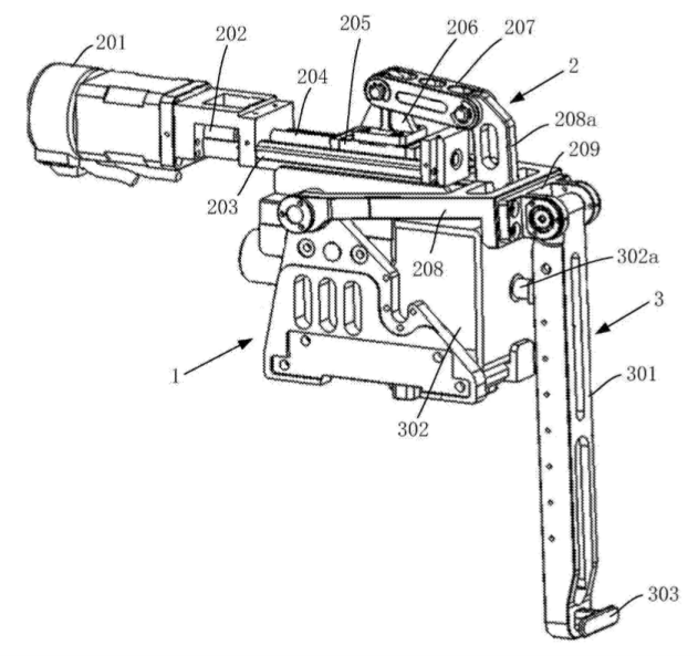
Figure 2.4 Simplified Ejection Mechanism
Hardware
In wheeled robot soccer matches, the shooting mechanism plays a decisive role, and its performance directly determines the match results. Currently, the main shooting mechanisms are pneumatic, spring-based, and electromagnetic. Electromagnetic mechanisms are preferred by most teams due to their simple and reliable structure, controllable kicking force, and other advantages. For example, Jiangxi University of Science and Technology has proposed a pneumatic ejection device that mounts a kicker in front and behind the robot. It uses compressed CO2 and cylinders as the ejection medium, utilizes recycled small steel cylinders to store CO2, and employs electromagnetic valves to control the release of CO2 gas. North University of China has developed a spring-based ejection mechanism, where a gear-cam compresses the spring, and an encoder determines when the cam lifts the kicking rod to fully reset the spring. Beijing Information Science & Technology University has designed an electromagnetic ejection device, as shown in Figure 2.6. This ejection mechanism offers fast response, high kicking power, and stability.
Software Strategy
Real-time visual perception: Implementing omnidirectional vision involves several steps, including distance calibration, pixel-level color segmentation, and optimization algorithms for self-localization and target localization. It also incorporates lower-level perceptual information such as odometry and gyroscopic data to improve the accuracy of self-localization and object localization.
Distributed communication system: Building the ROS (Robot Operating System) architecture, as shown in Figure 2.7, ROS is a highly flexible software framework used for developing robot software programs. It includes a wide range of tools, libraries, and conventions aimed at simplifying the development of complex and robust robot behaviors across different robotic platforms. ROS can be summarized as “ROS = Plumbing + Tools + Capabilities + Ecosystem,” signifying its role in communication mechanisms, toolkits, high-level robot capabilities, and the broader robot ecosystem. ROS enables communication between robots and provides endless possibilities for functionality expansion.
Object localization and mapping: Research and application of SLAM (Simultaneous Localization and Mapping) technology, robot localization involves estimating the robot’s pose given a known map, while mapping involves creating an environmental map given the robot’s pose. SLAM technology, despite its main purpose being mapping, continually updates its pose information while mapping to achieve more accurate mapping results. In GPS-denied indoor environments, SLAM technology allows robots to map unknown environments, serving as the foundation for autonomous navigation technology.

Figure 2.5 ROS Composition
3. Research Foundation
3.1 Mechanical Structure Design
3.1.1 Mobile Platform Design
We use four mutually orthogonal uniformly distributed omnidirectional robot chassis and four omnidirectional wheels as the moving components of the robot. The four wheels ensure the stability of the chassis while moving. In the production of omnidirectional wheels, we independently design the overall structure of the omnidirectional wheel system and apply for a patent. It is used to ensure the stability of the omnidirectional wheel when rotating and protect the motor shaft, greatly reducing the damage to the motor shaft during the rotation of the omnidirectional wheel, solving the problem of different axes between the motor shaft and the omnidirectional wheel, and initially simulating the omnidirectional movement of the platform through motion examples. Designing omnidirectional wheels requires high coaxiality, high friction coefficient of large wheels, and flexible rotation of small wheels; the chassis should be heavy and rigid, so that the center of gravity of the entire platform moves downward. Considering that there will be a lot of confrontation and fierce collision in the actual competition process, all the materials of the mobile platform are made of stainless steel sheets and aluminum alloy panels. Finally, by controlling the four omnidirectional wheels, the platform’s omnidirectional movement is achieved. As shown in Figure 3.1.
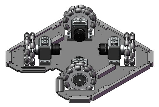
Figure 3.1 Mobile Platform
In the competition of wheeled soccer robots, the quality of chassis movement is the key factor that determines victory. The movement effect of the chassis and the stability of the wheels are closely related to the existing technology. Most of the existing technology designs have the disadvantages of simple structure, poor stability of movement, wear on the motor shaft, and movement deviation, which restrict the mobility of soccer robots.
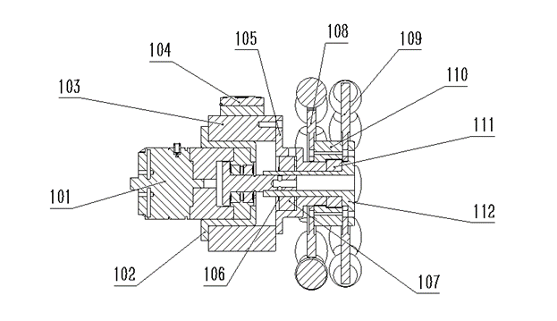
Figure 3.2 Omnidirectional Wheel Mechanism
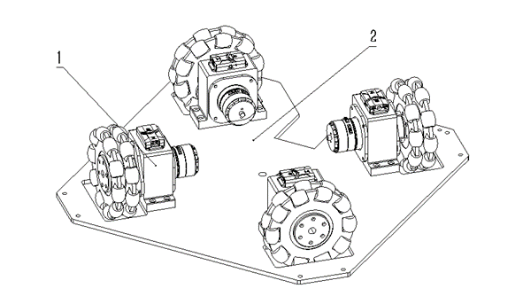
Figure 3.3 Mobile Chassis
An omnidirectional wheel system as an integral structure, comprising an omnidirectional wheel system as an integral structure (1) and a bottom plate (2); the omnidirectional wheel system as an integral structure (1) is mounted on the bottom plate (2); the omnidirectional wheel system as an integral structure (1) and the bottom plate (2) are both mounted on the bottom of the soccer robot; under the control of the electronic controller (104), the omnidirectional wheel can be rotated and driven by the transmission flange (112) to achieve movement of the platform.
The omnidirectional wheel system as an integral structure (1) includes a motor (101). Under the control of the electronic controller (104), the motor (101) is driven to rotate. At the same time, the motor (101) cooperates with a transmission flange (112), which can drive the transmission flange (112) to rotate. The motor (101) has the characteristics of large torque and high speed, which can effectively achieve the rotation of the omnidirectional wheel.
The omnidirectional wheel system as an integral structure (1) includes a motor fixing piece (102), which can fix the motor (101). The motor fixing piece (102) simultaneously fixes and cooperates with a connecting flange (103) on the connecting flange (103).
The omnidirectional wheel system as an integral structure (1) includes a connecting flange (103), which is fixed and cooperated with the bottom plate (2). When the omnidirectional wheel drives the bottom plate (2) to move, it can effectively fix the position of the omnidirectional wheel.
The omnidirectional wheel system as an integral structure (1) includes an electronic controller (104), which is fixed and cooperated with the upper end of the connecting flange (103) and can control the motor (101).
The omnidirectional wheel system as an integral structure (1) includes a transmission flange fixing piece (105), which is fixed and cooperates with the connecting flange (103), and cooperates with a bearing (107) at the same time.
The omnidirectional wheel system as an integral structure (1) includes a bearing clip (106) and a bearing (107). The bearing clip (106) cooperates with the transmission flange (112) to limit the bearing (107). The bearing (107) cooperates with the transmission flange fixing piece (105) through three threaded holes, and when the motor (101) drives the transmission flange (112), the bearing (107) can effectively reduce the friction between the transmission flange (112) and the transmission flange fixing piece (105).
The omnidirectional wheel system as an integral structure (1) includes two wheel hubs (1) 108 and wheel hubs (2) 109. The two hubs are formed into an omnidirectional wheel structure through separate coupling with the omnidirectional wheel coupler (110). Among them, the omnidirectional wheel hub (2) 109 is fixedly cooperated with the transmission flange (112).
The omnidirectional wheel system as an integral structure (1) includes an omnidirectional wheel coupler (110), which is fixedly cooperated with the omnidirectional wheel hub (2) 109, and then cooperates with the transmission flange (112) and the thrust ball bearing (111).
The omnidirectional wheel system as an integral structure (1) includes a thrust ball bearing (111), which is cooperated with the transmission flange (112) and contacts the transmission flange fixing piece (105) to reduce the lateral friction generated during movement.
The integral structure (1) of the omnidirectional wheel system includes a transmission flange (112) that is fixedly coupled with the omnidirectional wheel hub (2) 109. After the thrust ball bearing (111), it cooperates with the transmission flange fixing piece (105) and the bearing (107), and is limited by the bearing clip (106).
Preferably, the motor (101) is fixedly coupled to the motor fixing piece (102); the motor fixing piece (102) is fixed on the connecting flange (103); the connecting flange (103) is fixed on the bottom plate (2).
Preferably, each set of four omnidirectional wheel system integral structures is matched with one bottom plate.
3.1.2 Design of the Kicking Mechanism
For medium-sized soccer robots, the kicking mechanism is the core of the entire robot’s kicking function. When choosing a kicking mechanism, it should have characteristics such as short response time, sufficient kicking force, and fast kicking speed. Taking all factors into consideration, we plan to use an electromagnetic propulsion method and design the corresponding mechanical structure to achieve the kicking action of the soccer robot. According to real human soccer matches, we find that straight shots and chip shots are two important ways to score goals. To achieve both straight shots and chip shots, we use a ball screw stepper motor to move the kicking rod up and down, thereby changing the kicking point to achieve straight shots and chip shots at different angles. After continuous optimization and design, we have designed a kicking mechanism that not only meets the above requirements but also has the advantages of high reliability, easy maintenance, and easy disassembly and assembly. As shown in Figure 3.4.
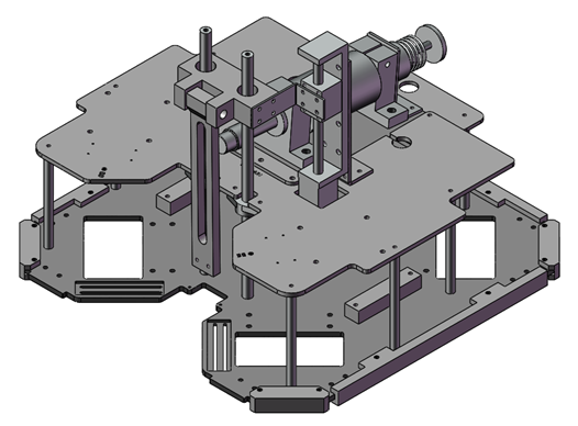
Figure 3.4 Kicking Mechanism
In the competition of wheeled soccer robots, scoring goals plays a decisive role. The electromagnetic kicking system is an important part of the robot, including pneumatic, spring, and electromagnetic kicking systems. The electromagnetic kicking system is widely used due to its controllable force and high stability. However, existing kicking systems can only kick the soccer ball in a fixed direction and cannot perform chip shots, lob shots, and other technical movements. At the same time, the existing electromagnetic kicking systems use flyback diodes to solve the problem of strong induced electromotive force when the coil is de-energized. During this process, the stored magnetic energy in the coil is released in the form of heat, resulting in some energy wastage.

Figure 3.5 Kicking Mechanism Design
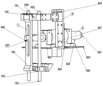
Figure 3.6 Kicking Mechanism Design
To overcome the shortcomings of existing technology, a soccer robot electromagnetic kicking system with a half-bridge circuit energy recovery is provided. The system includes a mechanical structure and a control circuit. The mechanical structure includes a kicking structure, an electromagnetic propulsion structure, and a lifting structure. The control circuit uses a half-bridge circuit to control the action of the electromagnetic propulsion structure, drive the kicking mechanism to perform kicking actions, and control the lifting mechanism to move the kicking mechanism up and down in the vertical direction, changing the position of the kicking point to achieve multiple-angle kicks. After the kicking action is completed, the control circuit can recover the magnetic energy of the electromagnetic coil, improve energy utilization efficiency, and reduce waiting time for capacitor charging.
As shown in Figures 3.5 and 3.6, a soccer robot electromagnetic kicking system with half-bridge circuit energy recovery includes a mechanical structure and a control circuit. The control circuit controls the mechanical structure to perform kicking actions.
The mechanical structure includes a kicking structure (1), an electromagnetic propulsion structure (2), and a lifting structure (3). The electromagnetic propulsion mechanism (2), under the control of the control circuit, drives the kicking structure (1) to perform kicking actions. The lifting mechanism (3) controls the vertical movement of the kicking structure (1), changing the position of the kicking point to achieve multiple-angle kicks.
The control circuit uses a half-bridge circuit structure, including the first insulated gate bipolar transistor, the second insulated gate bipolar transistor, the first fast recovery diode, the second fast recovery diode, the electromagnetic coil, and a 500V capacitor.
The collector of the first insulated gate bipolar transistor is connected to the positive pole of the 500V capacitor, and the cathode of the first fast recovery diode is connected to it. The emitter of the first insulated gate bipolar transistor is connected to the cathode of the second fast recovery diode. The collector of the second insulated gate bipolar transistor is connected to the anode of the first fast recovery diode, and the emitter of the second insulated gate bipolar transistor is connected to the negative pole of the 500V capacitor, with the anode of the second fast recovery diode connected to it. One end of the electromagnetic coil is connected to the emitter of the first insulated gate bipolar transistor, and the other end is connected to the collector of the second insulated gate bipolar transistor.
When the first insulated gate bipolar transistor and the second insulated gate bipolar transistor turn on, the electromagnetic coil generates magnetic force to drive the electromagnetic propulsion structure’s action. When the first insulated gate bipolar transistor and the second insulated gate bipolar transistor turn off, the remaining magnetic energy in the electromagnetic coil is recovered as electrical energy in the 500V capacitor.
Preferably, the kicking structure (1) includes a push rod bracket (101), a kicking rod (102), a push rod fixing flange (103), a push rod (104), and a pivot (105). The push rod (104) is vertically positioned, with its upper end fixed by the push rod bracket (101) and its lower end fixed by the push rod fixing flange (103). The kicking rod (102) is located on the outside of the push rod (104), parallel to it, and its upper end is connected to the push rod bracket (101) via the pivot (105), with its lower end suspended. The kicking rod (102) has a slot and rotates around the pivot (105) under the drive of the electromagnetic propulsion structure (2), lifting the lower end to perform the kicking action.
Preferably, the electromagnetic propulsion structure (2) includes a pullback collar (201), an electromagnetic mechanism (202), a placement plate (203), a connecting rod (204), a fixed flange (205), a kicking transmission component (206), and a pin (207). The fixed flange (205) is mounted on the middle sides of the electromagnetic mechanism (202), and the fixed flange (205) is fixedly connected to the placement plate (203) above it. The pullback collar (201), the electromagnetic mechanism (202), the connecting rod (204), and the kicking transmission component (206) are sequentially fixedly connected. The kicking transmission component (206), which is not fixedly connected to the connecting rod (204) at the other end, passes through the slot in the kicking rod (102) and is fixed with a pin (207). Under the control of the control circuit, the electromagnetic mechanism (202) pushes the kicking rod (102) to rotate around the pivot (105) through the connecting rod (204) and the kicking transmission component (206) to perform the kicking action. After the kicking action is completed, the pullback collar (201) retracts, driving the electromagnetic mechanism (202), connecting rod (204), and kicking transmission component (206) to return, resetting the kicking rod (102).
Preferably, the lifting structure (3) includes a stepper motor linear structure (301), a stepper motor connector (302), a stepper motor guide rail module (303), and a fixed sheet (304). The fixed sheet (304) is fixedly connected to the placement plate (203) and is fixedly connected to the stepper motor linear structure (301) and secures the stepper motor linear structure (301). One end of the stepper motor connector (302) is fixedly connected to the push rod bracket (101), and the other end is fixedly connected to the stepper motor guide rail module (303). The stepper motor guide rail module (303) is engaged with the stepper motor linear structure (301) through a screw and nut, and the stepper motor linear structure (301) drives the stepper motor guide rail module (303) to move up and down. The stepper motor connector (302) drives the push rod bracket (101) and the kicking rod (102) to move up and down, changing the kicking position in height and achieving multi-angle kicking.
3.1.3 Ball Handling Mechanism Design
For medium-sized soccer robots, the ball handling mechanism is essential to smoothly transport the ball to the target area. The ball handling mechanism is designed to consist of two parts - the active part and the passive part. The active part employs the M3508 motor to drive the active friction wheel and transmits torque through a conveyor belt, saving front space on the robot. The passive part utilizes small rollers as passive friction wheels, fixed on the bottom plate, and capable of omnidirectional movement, eliminating the disadvantages of traditional single-axis friction wheels that affect ball rotation. The entire design is modular, facilitating maintenance and installation. The active ball handling mechanism uses an angle sensor and M3508 motor, which rotate on different axes. This allows the M3508 motor to drive the conveyor belt around a synchronous pulley while the active friction wheel grabs the ball. This action generates angle change signals, allowing the control circuit to adjust motor speed and torque based on these signals, thus improving ball control. The bottom of the ball handling mechanism also features adjusting screws to determine the initial position of the ball handling mechanism, making it easier to select the optimal position for ball gripping during actual adjustments.
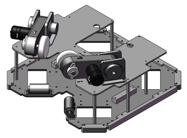
Figure 3.7 Ball Handling Mechanism
In the context of wheel-type soccer robot competitions, the quality of ball handling plays a pivotal role in determining victory. Existing technologies often suffer from complex structures, poor ball handling stability, and instances of robots losing control of the ball during maneuvers, all of which limit the agility of soccer robots.
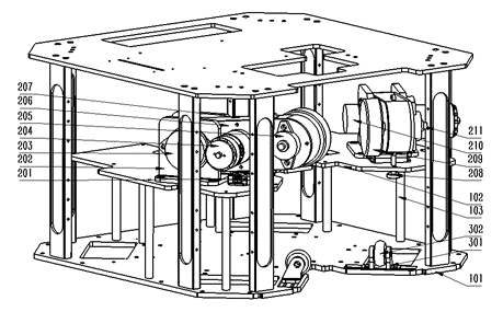
Figure 3.8 Active Ball Handling System
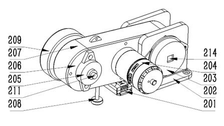
Figure 3.9 Exploded View of the Active Ball Handling System (Part 1)
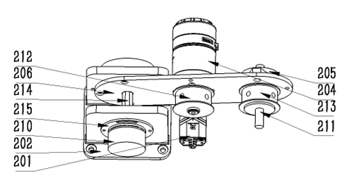
Figure 3.9 Exploded View of the Active Ball Handling System (Part 2)
This system comprises fixed fixtures, an active ball handling mechanism, a passive ball handling mechanism, and a control circuit. The active and passive ball handling mechanisms are fixed on the fixed fixtures. The active and passive mechanisms work in tandem to produce excellent ball handling results. The control circuit regulates the active ball handling mechanism to achieve stable ball handling in various scenarios. This system enhances the maneuverability of soccer robots, featuring a simple design and excellent stability.
Active Ball Handling System for Soccer Robots
An active ball handling system for soccer robots comprises a fixed fixture 1, an active ball handling mechanism 2, a passive ball handling mechanism 3, and a control circuit. The fixed fixture 1 is installed inside the soccer robot. Both the active ball handling mechanism 2 and the passive ball handling mechanism 3, along with the control circuit, are fixed on the fixed fixture 1. The active ball handling mechanism 2 collaborates with the passive ball handling mechanism 3 to perform ball handling actions. The control circuit regulates the active ball handling mechanism 1, achieving stable ball handling in the soccer robot system.
The active ball handling mechanism 2 includes an angle sensor 210. When the soccer robot is handling the ball, changes in the ball’s position cause variations in the angle measured by the angle sensor 210, generating angle change signals. These angle change signals are transmitted to the control circuit, which uses them to determine the position of the soccer ball.
The passive ball handling mechanism 3 consists of a passive wheel 302. The passive wheel 302 remains in contact with the soccer ball during ball handling by the soccer robot. As the soccer ball rotates, the passive wheel 302 consistently provides support towards the center of the soccer ball, maintaining ball possession.
Optionally, the fixed fixture 1 comprises a bottom plate 101, a middle-layer partition 102, and aluminum columns 103. The aluminum columns 103 support the space between the bottom plate 101 and the middle-layer partition 102.
In an optional configuration, the active ball handling mechanism 2 also includes components such as a C620 brushless motor controller 201, a flange 202, a bidirectional disc damper 203, an M3508 brushless motor 204, a horizontal bearing seat 205, a motor mounting plate 206, a conveyor belt protection housing 207, knurled screws 208, an active friction wheel 209, a non-standard shaft 214, and a GTC flange 215. The flange 202 is fixed to the bottom of the middle-layer partition 102. The angle sensor 210 is attached to the GTC flange 215 and secured to the flange 202. The non-standard shaft 214 is inserted into the angle sensor 210. The M3508 motor 204’s motor shaft passes through the hole in the middle of the motor mounting plate 206 and connects with the synchronous pulley 212. The horizontal bearing seat 205 contains bearings and passes through the shaft 211, as well as through another synchronous pulley 213. The synchronous belt connects the two synchronous pulleys. The conveyor belt protection housing 207 is fixed on the motor mounting plate 206, extending forward through the light shaft 211 of the horizontal bearing seat 205 and securing to the active friction wheel 209. It extends backward through the non-standard shaft 214. The angle sensor 210, GTC flange 215, and bidirectional disc damper 203 are positioned on either side of the flange 202, while the motor mounting plate 206 and the conveyor belt protection housing 207 are located between the two vertical plates of the flange 202.
Optionally, an L-shaped fixed structure is equipped with limit slots 210. After the L-shaped short end of the fixed column 203 passes through the limit slots 210, it connects with the non-standard shaft 214. During ball handling by the soccer robot, the movement range of the fixed column 203 is constrained by the limit slots 201, ensuring that the soccer ball remains within a controllable range.
Additionally, the passive ball handling mechanism 3 comprises an acute-angle base 301, which is securely connected to the bottom plate 103. The omnidirectional wheel 302 is fixed on the acute-angle base 301 and can rotate freely in all directions.
Furthermore, the active ball handling system for soccer robots can include two sets of active ball handling mechanisms 2 and two sets of passive ball handling mechanisms 3. The two sets of active ball handling mechanisms 2 are symmetrically arranged with respect to the central axis of the fixed fixture 1. Likewise, the two sets of passive ball handling mechanisms 3 are symmetrically arranged with respect to the central axis of the fixed fixture 2.
Finally, it’s worth noting that there are eight aluminum columns 103 between the middle-layer partition 102 and the bottom plate 101.
The active ball handling mechanism 2 includes an angle sensor 210. When the soccer robot is handling the ball, changes in the ball’s position cause variations in the angle measured by the angle sensor 210, generating angle change signals. These angle change signals are transmitted to the control circuit, which uses them to determine the position of the soccer ball.
The passive ball handling mechanism 3 consists of a passive wheel 302. The passive wheel 302 remains in contact with the soccer ball during ball handling by the soccer robot. As the soccer ball rotates, the passive wheel 302 consistently provides support towards the center of the soccer ball, maintaining ball possession.
3.2 Hardware Structure Design
Technical Approach:
1. Adoption of a control method combining upper and lower computers: The upper computer uses the ROS system on a computer platform, developed based on the QT development platform, to recognize the target object and make decisions about the robot’s actions. The lower computer uses an STM32F4xxx series microcontroller, as shown in the schematic diagram in Figure 3.10. It employs a PID control algorithm, which calculates the current traveling speed and travel angle, introduces negative feedback closed-loop control, reduces errors with respect to the initial travel angle, and simultaneously enhances speed control accuracy to improve the motion precision of the mobile robot during movement. MATLAB simulations of PID algorithm for position control are shown in Figure 3.11, and MATLAB simulations of PID algorithm for speed control at specific points are shown in Figure 3.12.
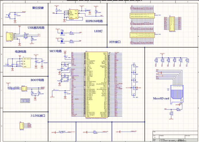
Figure 3.10 Schematic Diagram of STM32F4xxx Series Microcontroller
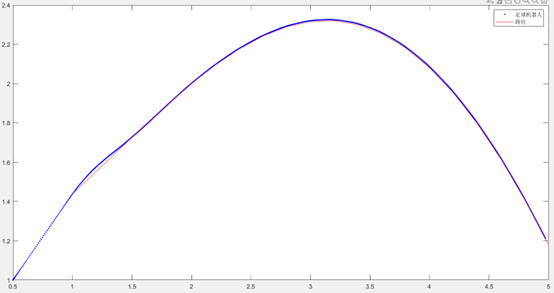
Figure 3.11 Soccer Robot Position Control
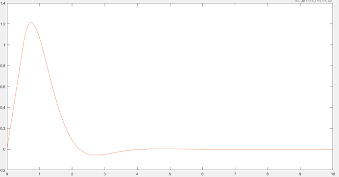
Figure 3.12 Soccer Robot Speed Control
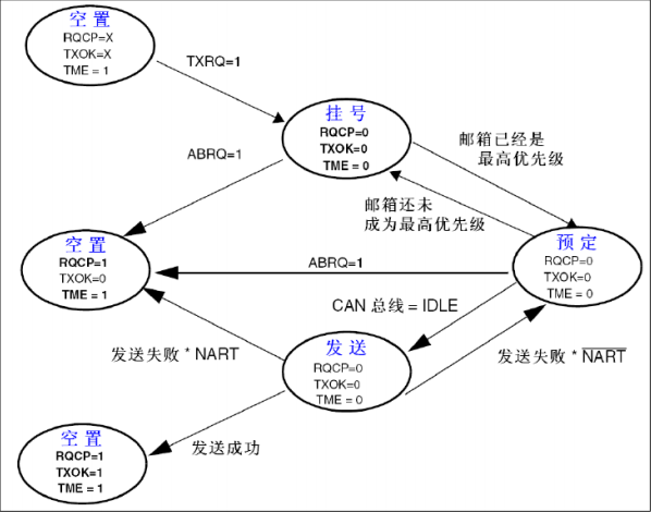
2. Utilization of the CAN communication protocol for motor control: The CAN protocol is widely used in various automation and industrial production control applications and is one of the most widely used fieldbuses in the world. The CAN bus transmission process is shown in Figure 3.13, and the CAN bus reception process is shown in Figure 3.14.
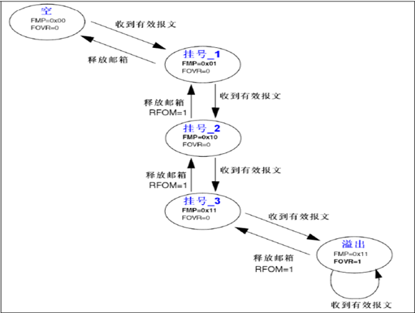
Figure 3.13 CAN Bus Transmission Process
Translation:
3.14 CAN Reception Process
3. The circuit boards of this system are designed using Altium Designer software. The circuit board employs a modular design, which ensures the stable and reliable operation of the system. In case of problems, the root cause can be quickly identified by replacing the corresponding module. This not only saves time but also reduces costs. We have independently designed and manufactured the power management module and the main control chip module. We utilize a switching voltage regulator chip to provide different voltages to the main control chip, drive module, and motors while incorporating protective circuits with overcurrent and short-circuit protection. The main control chip module integrates multiple modules such as screen display, mode switching, joystick control, and multi-protocol communication, as shown in Figure 3.15. The power management module is depicted in Figure 3.16.
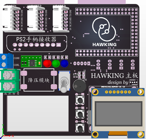
Figure 3.15 Main Control Chip Module
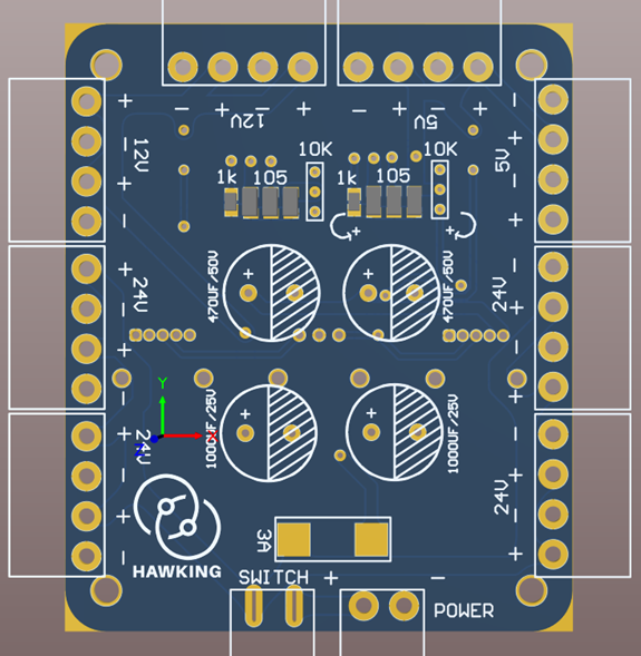
Figure 3.16 Power Management Module
4. Utilization of Zigbee high-speed communication: Based on the principle of serial communication, this approach enables communication between the robot and the upper computer. Both the upper and lower computers perform tasks and communicate, effectively improving fault tolerance and interference resistance mechanisms.
5. Data communication protocol: We have developed a proprietary communication protocol that incorporates an error feedback mechanism. It encapsulates transmitted information as payload, adding frame headers, frame tails, and checksums. This, to some extent, reduces erroneous data and enhances communication quality. A baud rate of 115200 is used, and the upper and lower computers use the same data packet format (classification instruction start and end flags, and parity at the end) to ensure data transmission accuracy.
6. The motors employ closed-loop speed control, with encoder feedback to adjust the motor’s PID, enabling precise control of the motor’s speed. Different control modes have been designed for use on different surfaces. These modes can control the motor by adjusting parameters such as current and voltage. Additionally, we can send commands to the motor controller via CAN communication, which then generates PWM signals to control the motor. In certain high-precision scenarios, we can control the motor to ensure that all three motors have exactly the same speed. Furthermore, we can precisely control the motor’s rotation angle and revolutions. This allows for precise control of the distance traveled by the vehicle and the angles it turns, ensuring accurate control of the vehicle.
Hardware Devices:
ZED Module: A 2K stereo camera used for target localization and detection, providing depth information for detecting the position of the target robot. The ZED module is shown in Figure 3.17.
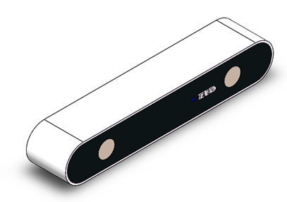
Figure 3.17 ZED Stereo Camera Module
Linear Displacement Sensor: The KTR self-recovery displacement sensor, a high-precision and high-sensitivity displacement sensor, is used to accurately determine whether the ball-handling motor has successfully gripped the ball. The linear displacement sensor module is depicted in Figure 3.18.
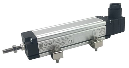
Figure 3.18 Linear Displacement Sensor Module
Gyroscope: The HI216 six-axis attitude sensor provides three-dimensional orientation data based on local geographic coordinates, including roll angle, pitch angle, and relative heading angle, calculated through sensor fusion algorithms. This data is transmitted to the core control board of the microcontroller via serial communication, correcting the robot’s travel speed and direction.
TX2 Embedded Development Board: A supercomputer in the field of embedded systems, the TX2 can handle larger and more complex deep neural networks, offering high-speed computing performance in a highly flexible and scalable platform. It serves as a solid foundation for vision processing in wheeled robot systems. The TX2 is shown in Figure 3.19.
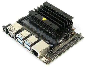

Figure 3.19 RPLIDAR A2 Lidar
3.3 Software Structure Design
Our wheeled robot software primarily consists of the following modules:
| Main Technology | Software Components | Main Theories (not exclusive) |
|---|---|---|
| Real-time Vision Perception | Vision | Computer Vision, Deep Learning |
| Distributed Communication System | World Model worldmodel | Computer Networking, Databases, Operating Systems |
| Object Localization and Mapping | World Model worldmodel | Information Fusion |
| Path Planning and Autonomous Obstacle Avoidance | Strategy Strategy | Numerical Analysis, Machine Learning |
| Role Assignment and Strategy Control | Strategy Strategy | Algorithm Design, Reinforcement Learning |
Figure 3.21 Software Modules of the Wheeled Robot
Real-time Visual Perception - Omnidirectional Vision Module
- The implementation of omnidirectional vision mainly involves the following steps:
- Distance calibration
- Pixel-level color segmentation
- Final matching optimization algorithm for self-positioning and target positioning
- Incorporating information from sensors such as odometers and gyroscopes to further improve the accuracy of self-positioning and target positioning. The following is a basic approach and technical roadmap for solving these problems:
-
Distance Calibration
Distance calibration primarily involves analyzing the optical geometry properties of the omnidirectional camera. By combining a known flat image of a regular field with the curved original image captured by the omnidirectional camera, we can transform the original image into a world plane view. By establishing an error table for the length of each point on the soccer ball to its nearest white point, we can regularize the white points in the original image to minimize errors in the world plane coordinates. This problem can be simplified into a task of minimizing an error function. Genetic algorithms can be used to solve this problem initially.
The task principles are as follows:
\[\begin{array}{cc} \theta_{o, p}=\theta_{o, p^{\prime}} & \text { Equation 3-1 }\\ d_{o, p}=q_1 \tan \left(q_2 \cdot d_{o, p^{\prime}}\right) & \text { Equation 3-2} \\ p^w=\left[\begin{array}{l} x+d_{o, p} \cos \left(\theta+\theta_{o, p \prime}\right) \\ y+d_{o, p} \sin \left(\theta+\theta_{o, p}\right) \end{array}\right] & \text { Equation 3-3 } \\ \operatorname{minj}=\sum_j^n \operatorname{error}\left(P_i^W\right) & \text { Equation 3-4 } \end{array}\]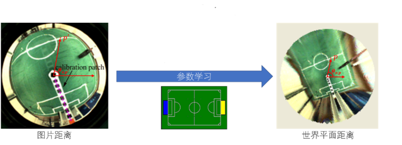
Figure 3.22 Task Principle Schematic
Further improvements in the accuracy of the reconstructed image can be achieved through classical image processing methods.
-
Color Segmentation
Due to the real-time and rapid image processing requirements for soccer robot matches, the speed of obtaining information about objects of specified colors using threshold comparison methods cannot meet the aforementioned requirements. Therefore, we employ a faster color classification method using a lookup table. This method determines the pixel’s color category by quickly looking up the result corresponding to multiple indexed coordinates in the query table. In panoramic vision, color segmentation can be used to implement object positioning and classification. When processing the value of a corresponding pixel, the category to which it belongs can be determined quickly by querying the lookup table:
In the soccer robot competition, various objects are clearly distinguished by their colors, as shown in the table below:
| Category | Color |
|---|---|
| Field | Green |
| Sideline | White |
| Robot/Obstacle | Black |
| Soccer Ball | Yellow |
| Goal 1 | Blue |
| Goal 2 | Yellow |
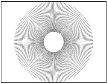
Figure 3.24 Robot Information Fusion Structure
We also perform a 360-degree scan of the panoramic vision image at every 1-degree interval for image processing. Sampling on the scan lines significantly reduces the computational load on the entire image. To meet the real-time requirements of robot competition, the angle step size for selecting scan lines can be dynamically adjusted based on the on-site conditions. Color segmentation employs a more friendly approach compared to RGB, incorporating the Y component of YUV space and the H and S components of HSI space with weighted matching to achieve more precise object recognition and reduce noise issues.
YUV has three components: “Y” represents luminance (Luminance or Luma), which corresponds to the grayscale value, while “U” and “V” represent chrominance (Chrominance or Chroma) and describe color and saturation, used to specify the pixel’s color.
HSI color space is designed based on the human visual system, using hue (Hue), color saturation (Saturation or Chroma), and intensity (Intensity or Brightness) to describe colors.
Due to changes in the surroundings of the field each year (external columns and other features) and the lack of internal field information, coupled with the scarcity of goal information within the field, we use a white line matching-based optimization algorithm to achieve global robot localization and self-localization.
We plan to further enhance color segmentation accuracy by combining other color space components and filtering methods.
- Reliable Identification of White Lines:
Due to variations in ambient light intensity and distribution, conventional color constancy methods like Retinex struggle to address uneven color distribution. Fusion of color spaces is used to address the challenges posed by changing lighting conditions, as meeting the increasing demand for real-time performance becomes difficult. However, the differences in brightness and color between the white lines and the green field have always been quite distinct. Considering these factors, we employ a scanline-based algorithm to identify white lines. This algorithm detects sudden changes in brightness and color between the field and the white lines (as shown in the figure below). Continuous improvement in accuracy is achieved through matching optimization. Additionally, this approach shares some of the scanline setup with the color segmentation algorithm, significantly reducing computational requirements.
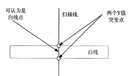
Figure 3.25 Principle of White Line Recognition
- Matching Optimization
To address the “robot kidnapping” problem and solve the issues of robot self-localization and global localization, we utilize the white line information on the field.
We take the white point information obtained from the aforementioned scanlines and calibrate the distances. Based on the robot’s position, we match the detected white points from color segmentation with the pre-established calibration image (as shown below). The results are combined with information from the odometry and gyroscope and are subject to local Kalman filtering optimization to obtain the robot’s final position.

Figure 3.26 Schematic Representation of the Competition Field
Matching optimization can be framed as a problem of minimizing a deviation criterion by defining an error function. The error function, based on preliminary research, takes the following form:
\[E_k(o) = \sum_{i=0}^n \left(1 - \frac{c^2}{c^2 + e(o_k^i)^2}\right), \quad k = 1 \ldots 165 \quad \text{Equation 3-6}\]During the soccer match, the matching optimization process can be simplified as follows:
-
Initialization with no prior information: Select the 5 smallest error items from the global 11x15 grid points as the coarse matching result, then recursively refine it locally.
-
Initialization with prior information: Perform local searches near the previous position.
-
Re-initialization when there is a significant deviation between the robot’s orientation estimation and the gyroscope’s orientation angle.
- Fusion with Kalman Filtering and Odometry Information
Taking into account the reduced accuracy of visual localization due to white point occlusion and vibration noise, we combine odometry information and visual data. The basic process is described as follows:
-
When visual uncertainty is high: Localization relies more on odometry information.
-
When visual accuracy is high: Localization relies more on visual information.
-
Further improvements in white line recognition reliability are planned by adjusting filtering methods.
Distributed Communication System - ROS Architecture
- ROS (Robot Operating System) Software Architecture
ROS is a highly flexible software architecture used for developing robot software programs. It includes a vast array of tools, library code, and convention protocols designed to simplify the complexity of creating complex and robust robot behaviors across robot platforms. ROS can be described as “ROS = Plumbing + Tools + Capabilities + Ecosystem,” which means ROS is a collection of communication mechanisms, toolkits, high-level robot skills, and a robot ecosystem. ROS provides endless possibilities for communication between robots and extending functionalities.
Figure 3.27 ROS Components
① Distributed and Modular
ROS is designed to be distributed and modular. Its modular nature forms the foundation for the project’s extensibility and autonomy. The core modules of the project can be selected from existing ROS software packages to extend the functionality based on user requirements. ROS also provides interfaces for writing custom modules, contributing to the project’s autonomy.
ROS’s distributed nature divides robot functionality into multiple modules and offers an integration point. This integration point provides access to hardware drivers, common robot functionality, development tools, useful external libraries, and more. This forms the basis for information processing and communication between different modules within the project.
② Strong Development Environment
In recent years, ROS has been widely used in the fields of industrial and service robotics, accompanied by a large user community worldwide. Within this community, users can contribute software packages, covering a wide range of areas from proof-of-concept implementations of new algorithms to industrial-grade drivers and functionalities. This creates a solid foundation for optimizing and advancing algorithms in the project.
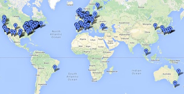
Figure 3.28 Distribution of ROS Users
③ High Degree of Freedom
Currently, the core software components of ROS are licensed under the standard three-clause BSD license. The BSD license is highly permissive, allowing users to modify and redistribute code and permitting the development of commercial software based on BSD code. This lays the foundation for commercial integration within this project.
④ International Perspective
ROS provides opportunities for networking and collaboration with world-class robot experts in the ROS community. This enables the project to have an international perspective, stay updated on cutting-edge robotic technologies through community interactions, and continually update and iterate on products.
Object Localization and Mapping - SLAM Technology
The localization problem for robots involves estimating the robot’s pose given a known map, while mapping refers to creating an environmental map given the known robot pose. SLAM (Simultaneous Localization and Mapping) technology primarily focuses on mapping but continuously updates the robot’s pose information during mapping. This leads to more accurate map updates based on improved pose information. In GPS-deprived indoor environments, SLAM technology enables robots to map unknown environments autonomously, forming the foundation of autonomous navigation technology.
- 2D Laser SLAM Algorithm - Cartographer Program Design
In this project, the open-source algorithm Cartographer is used for 2D grid map construction. Compared to the Gmapping algorithm, which relies on odometry accuracy, and the Hector SLAM algorithm, which relies on laser sensor accuracy, Cartographer algorithm provides better cost control and achieves low-cost high-precision SLAM mapping results. In this project, the goal is to port the Cartographer algorithm to ROS, use the Cartographer ROS package to implement the algorithm’s API interface through ROS communication mechanisms, and wrap it with ROS interfaces.
The Cartographer algorithm is based on the theory of graph optimization and consists of two main components: the frontend and the backend. The frontend is responsible for Scan-to-Submap matching and loop closure detection. It matches processed laser scan data with submaps. Additionally, when a submap is created, and no new data frames are inserted, local loop closure detection is performed. Once a submap is created, if the optimal match with the current estimated robot pose is found, a loop closure constraint is added. The backend optimizes many submaps generated by the frontend. Since frontend laser scan frames only match with the current submap, and the environmental map consists of a series of submaps, there can be cumulative errors. The Cartographer algorithm uses a sparse pose adjustment method to optimize the poses of all laser scan data frames and submaps. The adjustment aims to minimize the sum of errors between nodes, representing poses, subject to constraints. The mathematical expression for backend optimization using sparse pose adjustment is as follows:
\[\underset{\Xi^m}{\arg } \min _{\Xi^S} \frac{1}{2} \sum_{i j} \rho\left(E^2\left(\xi_i^m, \xi_j^S ; \sum_y \xi_{i j}\right)\right) \quad \text { Equation 3-7 }\]In the above equation, $ \Xi^m=\left{\xi_i^m\right}{\mathrm{i}=1 \ldots \mathrm{m}}, \quad \Xi^S=\left{\xi_j^S\right}{\mathrm{j}=1 \ldots \mathrm{n}} $ represent the poses of submaps and laser scan frames, respectively, under certain constraints. The relative pose 𝜉𝑖𝑗 represents the matching position of laser frame j in submap i, and together with its associated covariance matrix ∑𝑖𝑗, forms the optimization constraints. The cost function is represented by the residual E and can be calculated as shown.
To speed up loop closure detection and relative pose solving, Cartographer algorithm also uses a divide-and-conquer branch-and-bound scan matching algorithm to determine search windows for loop closure detection. The optimization results before and after backend optimization are shown in the following figure:
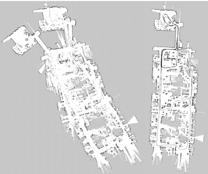
Figure 3.29 Comparison before (left) and after (right) backend optimization
- Path Planning and Autonomous Navigation Module:
With the global grid map provided by SLAM and sensor information, the robot can autonomously navigate towards a specified target in environments with obstacles. Autonomous navigation consists of three steps: determining the robot’s current pose, global path planning from the current position to the target point, and local path planning for the robot. This part of the program is mainly based on the navigation package in ROS, which includes global and local path planning, cost maps, map servers, and more. The overall structure of the package is as shown:
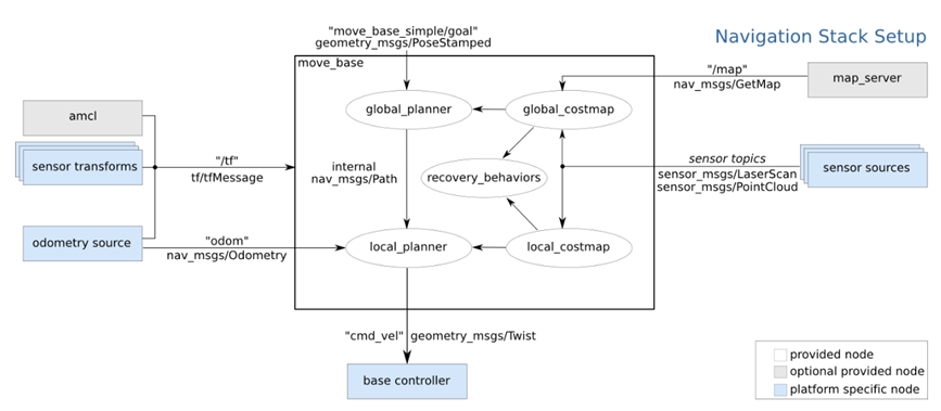
Figure 3.30 ROS Navigation Package Structure Diagram
- Adaptive Monte Carlo Localization (AMCL)
Adaptive Monte Carlo Localization (AMCL) is a probabilistic statistical localization method for mobile robots in 2D environments. It employs particle filtering algorithms to estimate the robot’s pose based on a known map, enhancing accuracy and expediting path planning. AMCL represents the probability distribution of the robot’s pose in the map using a certain number of particles, where denser particles indicate higher probability values. In the ROS navigation package, an application interface for the AMCL algorithm is provided. It takes /map and /scan information as input and initializes the AMCL particle filter by configuring various initialization parameters provided by ROS. Subsequently, the AMCL algorithm detects obstacles and estimates the robot’s pose in the map coordinate system.
4 Core Technologies
4.1 Electromagnetic Catapult System with Half-Bridge Circuit-Based Energy Recovery
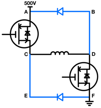
The electromagnetic catapult mechanism is illustrated in Figure 4.1. When a large current is passed through the coil, it generates a powerful magnetic field, attracting the silicon steel block to move forward. This movement drives the striker rod and the cushion block to impact the kicking plate. The upper part of the kicking plate is connected to the fixed structure through a pivot point and undergoes circular motion when subjected to force. The impact force is transmitted to the soccer ball through a nylon block attached to the lower part of the kicking plate. This design, with a certain degree of curvature in the front of the nylon block, increases the contact area compared to directly kicking the ball with the kicking plate, preventing damage to the soccer ball. When the power is turned off, the silicon steel block is returned to its initial position under the action of the rear spring (not shown in the diagram), preparing for the next kicking action. At the same time, the cushion block passes through the kicking plate and is fixed in place using a pin, which in turn drives the kicking plate back to its initial position.
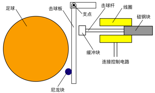
Figure 4.1 Schematic of the Electromagnetic Catapult Mechanism
The half-bridge circuit section of the catapult system is shown in Figure 4.2. The circuit consists of two IGBTs, two fast recovery diodes, and a coil. Considering that the peak current in the circuit can reach approximately 100A, the selected models are AUIRGPS4067D1 and RHRP3060. The intensity of the kicking action is controlled by the simultaneous switching of the two IGBTs. When both IGBTs are in the conducting state, the current flows from the positive terminal through A and C, passes through the coil to D and F, and returns to the negative terminal. This causes the coil to generate a magnetic force that propels the electromagnet into motion. When both IGBTs are rapidly turned off, a huge induced electromotive force is generated in the coil, driving the current from the negative terminal through E, C, passes through the coil to D, and B, and returns to the positive terminal. In traditional switch-controlled circuits, a single freewheeling diode is often used to protect the circuit from the damage caused by the enormous induced electromotive force, dissipating the energy from the electromagnet as heat. Using this circuit not only enables precise control of the on-off time of the electromagnet but also allows the residual energy in the electromagnet to be recovered into a capacitor for further use. Energy recovery enhances energy efficiency, reduces the charging time of the capacitor between kicks, and thus enhances the competitiveness of the soccer robot.
4.2 Half-Bridge Circuit Diagram
We created a simulation of the half-bridge circuit using Multisim software, as shown in Figure 4.3, to test the circuit’s performance. The x-axis represents time after the circuit is turned off, with a scale of 10 ms/div, and the y-axis represents capacitor voltage with a scale of 200 V/div. The simulation results are shown in Figures 4.4, 4.5, and 4.6.
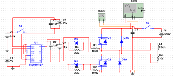
Figure 4.3 Simulation Circuit Diagram
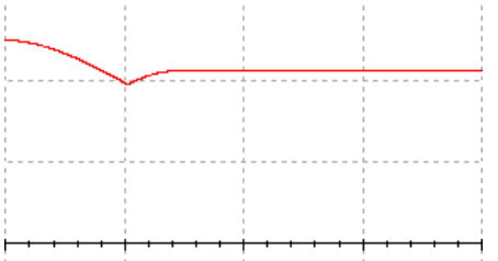
Figure 4.4 Image after 10ms of shutdown
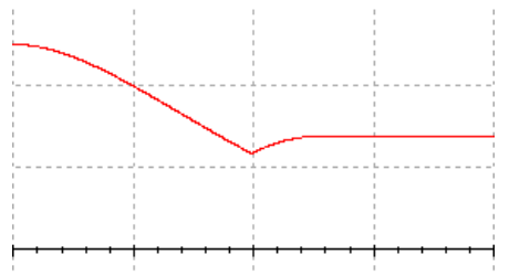
Figure 4.5 Image after 20ms of shutdown
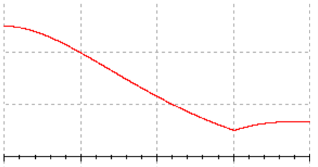
Figure 4.6 Image after 30ms of shutdown
From the simulation results, it is evident that during the discharge process, the capacitor voltage rises, with the maximum increase occurring when the voltage slope is at its steepest. The simulation results confirm the effectiveness of the circuit design.
4.2 Real-Time Visual Perception
In robot soccer competitions, wheeled robots are required to operate autonomously without any external intervention in aspects such as environmental perception, decision-making, motion control, and communication. This necessitates expertise in various fields, including computer vision, image processing, artificial intelligence, multi-robot collaboration, wireless network communication, digital circuits, and more. The visual system is crucial in robot soccer as it extracts valuable information from two-dimensional projections, models the real-world environment based on images, and generates control outputs. Through the visual system, it becomes possible to identify features such as the ball, the goal, and the robots of both teams, as well as their positions and orientations, thereby providing information to the decision-making system.
Considering our software architecture and hardware deployment, we conducted preliminary research on key techniques related to real-time visual perception.
4.2.1 Omnidirectional Vision - Self-Localization and Target Localization
The implementation of omnidirectional vision involves several key steps: distance calibration, pixel-level color segmentation, and optimization algorithms for self-localization and target localization. Additionally, low-level sensory information such as odometry and gyroscope data is fused to further improve the accuracy of self-localization and object localization results. Below are basic approaches and technical strategies for addressing these issues.
4.2.2 Forward Vision - Object Recognition and Localization
Object recognition algorithms in forward vision are primarily used to detect the soccer ball and robots from both the same team and the opposing team. Recognizing that panoramic vision may suffer from accuracy issues due to occlusions and imaging distortions, using a dedicated forward-facing camera can represent the same region with more pixels, especially improving the recognition of distant objects. Therefore, we plan to deploy the YOLOv3-Tiny network on the Nvidia Jetson TX2 embedded platform and train it using the National Defense Science and Technology University (NUDT) YouTube open-source dataset, as well as locally generated datasets, to obtain network parameters.
4.2.3 World Model - Coordinate Fusion
(1) Real-Time Database (RTDB) - CAMBADA
To facilitate communication between multiple robots, we have adopted an open-source real-time database called RTDB, developed by the CAMBADA team. The RTDB data structure allows all robots to share their local world models via IEEE 802.11b wireless networking.
(2) Coordinate Fusion and Map Construction
The ultimate purpose of the world model is to combine information perceived by multiple robots and construct a world map for strategy deployment and decision-making. To address this issue, we plan to achieve object position fusion through the world model phase. Initially, we ensure the stability of object trajectories based on extended Kalman filtering and estimate velocities based on linear regression.
4.3 Motion Control
In motion control, we employ a digital PID control algorithm. PID stands for Proportional-Integral-Derivative, and the PID control algorithm designs the controller’s output-to-input relationship as a combination of proportional, integral, and derivative terms in the software layer.
In position control, we use a positional PID algorithm. It is a discretized version of the analog PID algorithm using backward difference as follows:
\[u(t) \approx u(k), \quad e(t)=e(k) \quad \text{Equation 4-1}\] \[\int_0^1 e(t) dt=T \sum_{i=1}^k e(j), \frac{de(t)}{dt}=\frac{e(k)-e(k-1)}{T} \text{Equation 4-2}\] \[\text{Then}\] \[u(k)=K_p\left\{e(k)+\frac{T}{T_i} \sum_{j=1}^k e(j)+\frac{T_d}{T}[e(k)-e(k-1)]\right\}\] \[=K_p e(k)+K_i \sum_i^k e(j)+K_d[e(k)-e(k-1)] \text{Equation 4-3}\] \[K_i=K_P \frac{T}{T_i} \text{ - Integral coefficient, } K_d=K_P \frac{T_d}{T} \text{ - Derivative coefficient }\]The algorithm we use is based on the control flowchart shown in Figure 4.7.
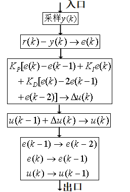
Figure 4.7 Flowchart of the Positional PID Algorithm Program
5 Innovations
-
Reduced error rates and improved error handling through a custom data communication protocol.
-
Fully self-designed electromagnetic catapult system based on a half-bridge circuit, enhancing kicking performance.
-
Adoption of a hybrid control system, enabling wheeled robots to independently perform tasks such as dribbling and shooting, while also facilitating information exchange among robots through Zigbee communication modules for tasks like passing.
-
Introduction of CAN communication in lower-level communication, providing enhanced functionality and greater scalability, capable of accommodating up to 256 devices with CAN communication simultaneously.
-
Utilization of industrial-grade panoramic cameras for comprehensive 360-degree, no-blind-spot vision in image processing.
-
Design experience with various types of wheeled robots, capable of meeting diverse requirements.
-
Overcoming the limitations of traditional AGVs, which have high site requirements, poor localization accuracy, and accumulated errors over extended operation times, resulting in navigation issues. The robot can adapt to more complex environments and application scenarios.
-
Integration of multiple technologies, including SLAM mapping, autonomous navigation, and obstacle avoidance, into a unified system.
-
Autonomous modeling during mapping, combining data from laser rangefinders, depth cameras, and sonar to overcome deficiencies in mapping with a single sensor, such as excluding transparent or light-absorbing objects.
-
Application of machine learning to overcome shortcomings in traditional path planning algorithms. Traditional path planning algorithms like Dynamic Window approach often fail to generate reasonable routes in complex environments with many curves, leading to robot collisions with obstacles. We employ machine learning to consider both the shortest path and obstacle avoidance requirements, building a model that allows the robot to reach its destination smoothly even in complex environments.
References
[1] Ren, J. (2016). Research on the Design and Motion Control of Wheeled Soccer Robots (Doctoral dissertation, National University of Defense Technology).
[2] Cheng, Q. (2016). Research on Target Detection Methods for Wheeled Soccer Robots Based on RGB-D Camera (Doctoral dissertation, National University of Defense Technology).
[3] Yu, Z. (2017). Research on Goalkeeper Path Planning Methods for RoboCup Wheeled Soccer Robots (Doctoral dissertation, Changsha University of Science and Technology).
[4] Tang, P. (2016). Research on Learning Algorithms for Soccer Robot Behaviors (Doctoral dissertation, North China University of Technology).
[5] Lu, Z., Tian, K., Liu, S., & Li, B. (2015). Design of Control System for Soccer Robots’ Interaction Rules. Computer Simulation, 32(05), 368-373.
[6] Liu, Y., Cai, L., & Yang, Y. (2014). Design of Motion Control System for RoboCup Wheeled Soccer Robots. Machine Tool & Hydraulics, 42(03), 70-72+15.
[7] Wang, P., Yu, Y., & Ru, F. (2019). Role Modeling and Petri Net Control Strategy of Soccer Robots in Multiple Motion States. Science, Technology and Engineering, 19(22), 201-207.